TM Builders are a distinct group of components that use grids defined in Rhino to to generate various structural elements like beams, columns, braces, concrete panels, foundations.
1 Core Logic
TM Builders are a set of grasshopper components that use grids defined in Rhino to generate various structural elements.
The grids need to be defined in a specific order and given specific names that has been explained in this section further below.
These grids can be easily created using ‘TM Grid Builder’ component.
2 Grid Requirements
All components work on grids already defined in Rhino.
The object property ‘Names’ of the gridline houses a distinct name for each gridline.
For e.g. looking at the gridlines defined in the case study- ‘TM Steel Portal Frame’, the name property of grid line-‘A’ modelled at Rhino Z=0 is ‘A-2’.
Gridlines with such ‘Name’ properties can only be used with other ‘TM Builders’ components.
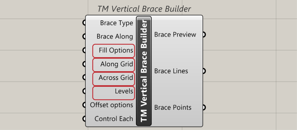
The gridline labels and their locations in terms of elevations are then used by certain inputs of the builder components which are:
- Element Along: if the builder is ‘TM Vertical Brace Builder’ then the input label shall be ‘Brace Along’
- Along Grid
- Across Grid
- Levels
- Fill Options
The above inputs form the core of the TM Builders components and have been explain below. ‘TM Vertical Brace’ component shall be used to explain the above inputs.
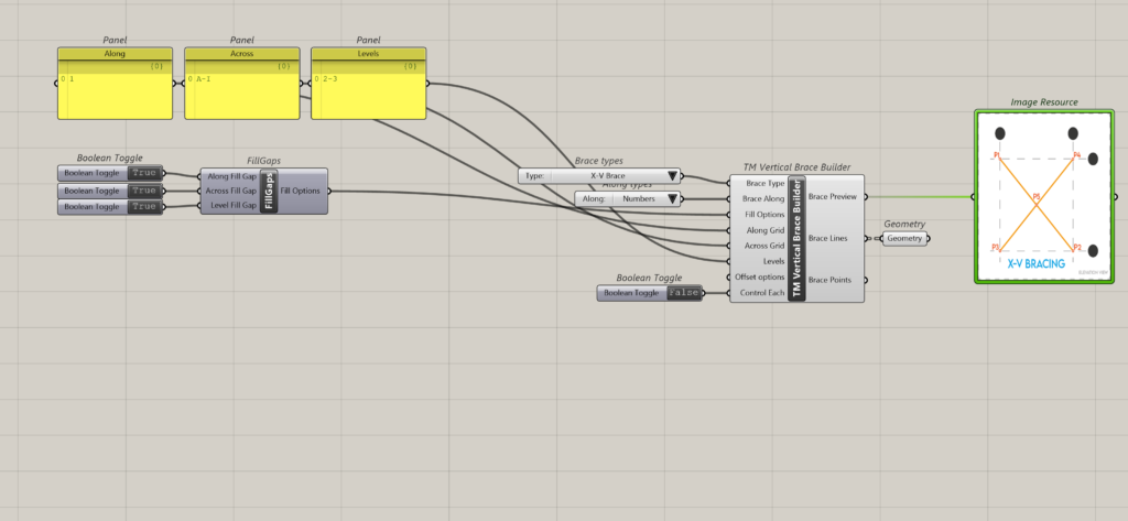
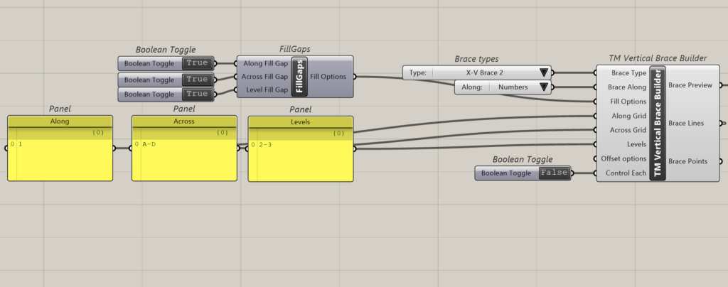
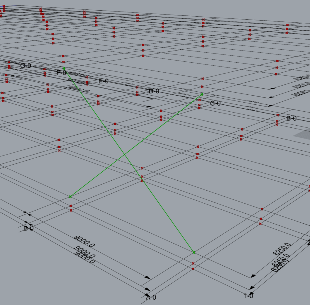
Inorder to create a vertical brace on gridline 1 between grids A to I and between levels 2-3 the following inputs shall have to be entered:
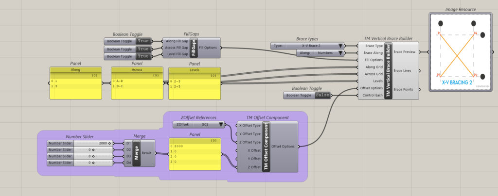
- Brace Type: X-VBrace
- Brace Along: Numbers
- Along Grid: 1
- Across Grid: A-I
- Levels:0-2
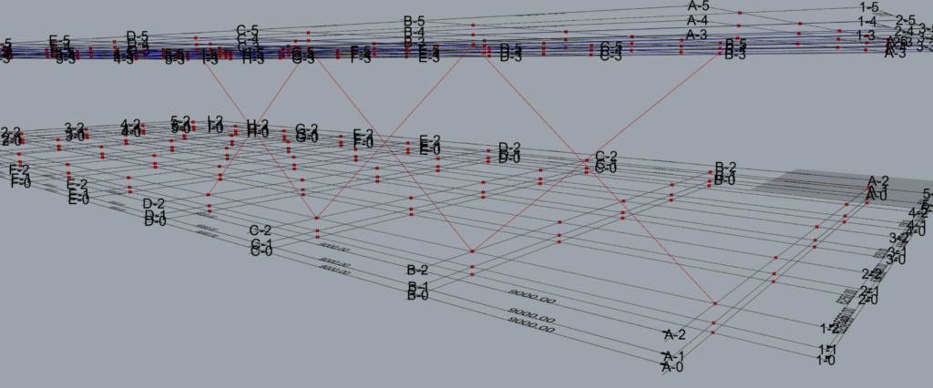
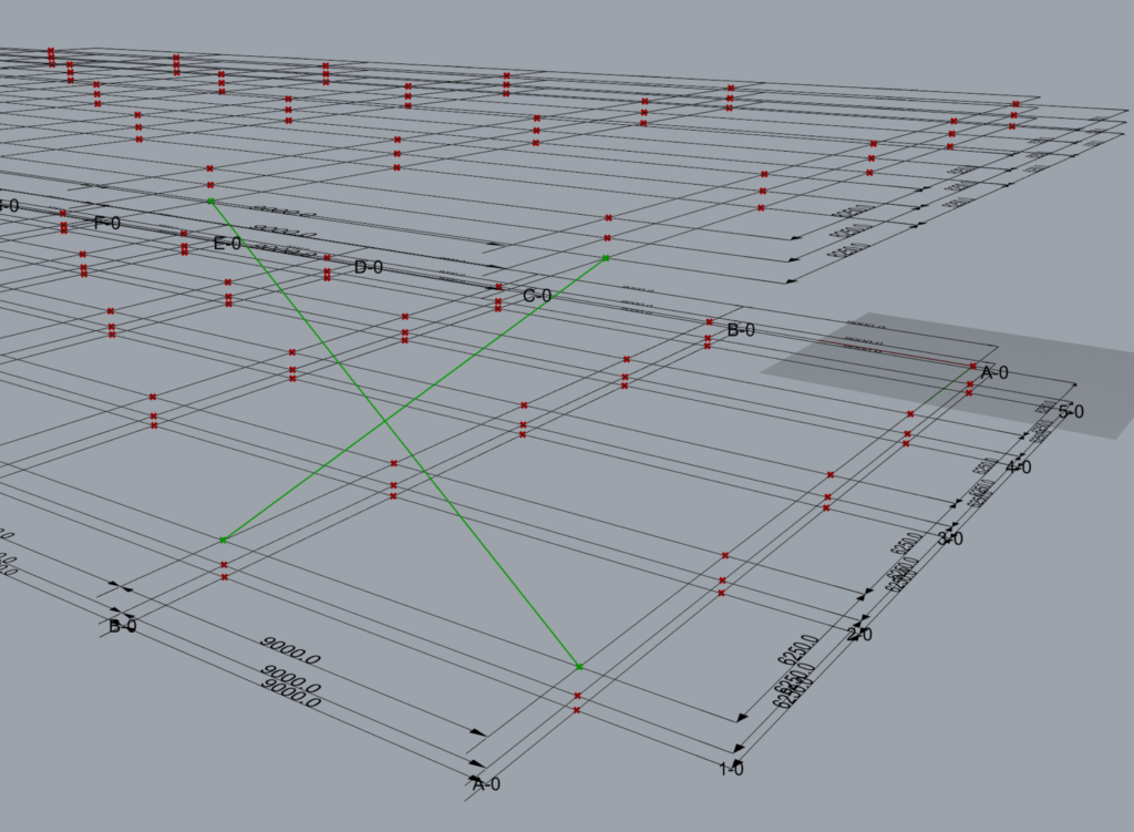
This creates the following output.
3 ‘Element’ Along
All the builders shall have this option which is a compulsory input. it will either be listed as ‘Brace Along’, ”Column Along’ etc.
A value list needs to be attached in which the following options shall be auto populated.
- Alphabet
- Number
This control decides which will be the governing grid series to ‘lay-out’ the structural elements.
The user has to select whether he wants to model the elements along alphabetical grids or numeral grids. This is particularly important for structural elements like plan braces, vertical braces etc.
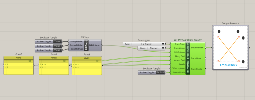
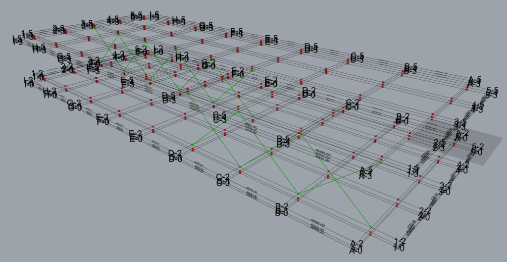
3.1 Alphabet
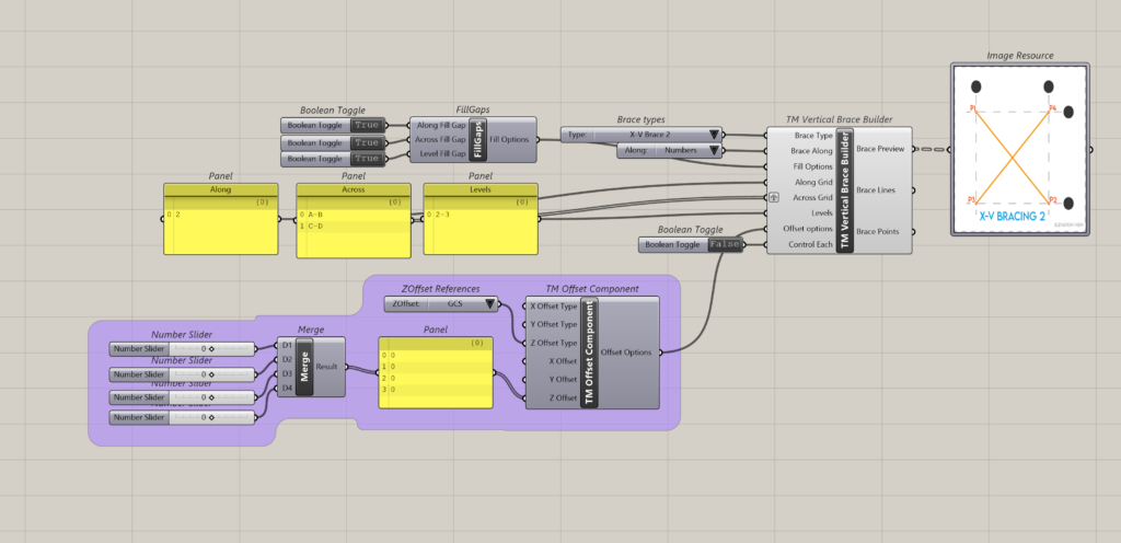
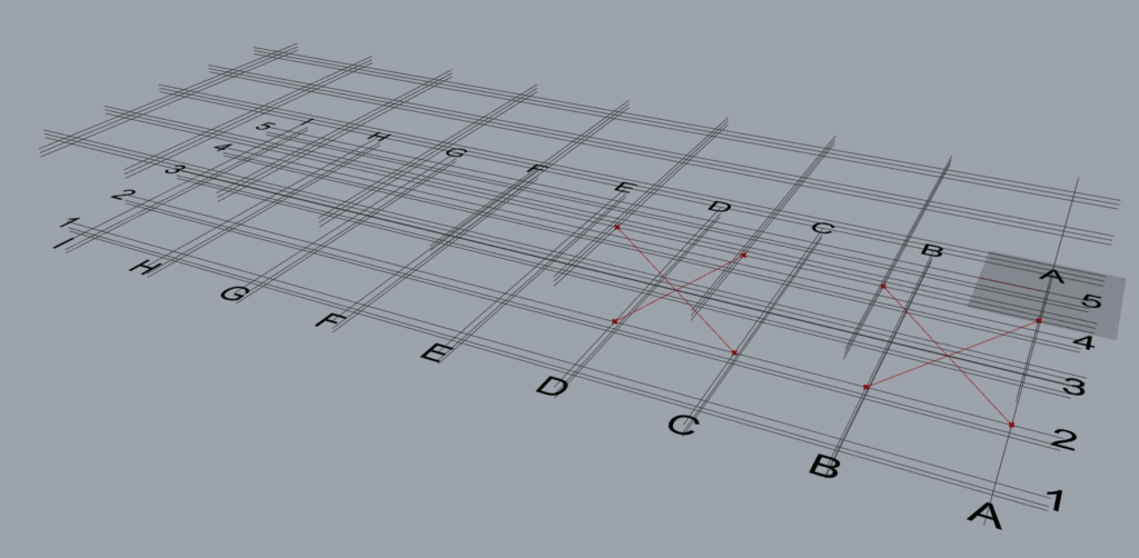
When the brace along input is ‘Alphabets’ then the braces shall be modelled along the alphabetical grid lines. Hence in the ‘Along Grid’ input only alphabets shall be fed by the user.
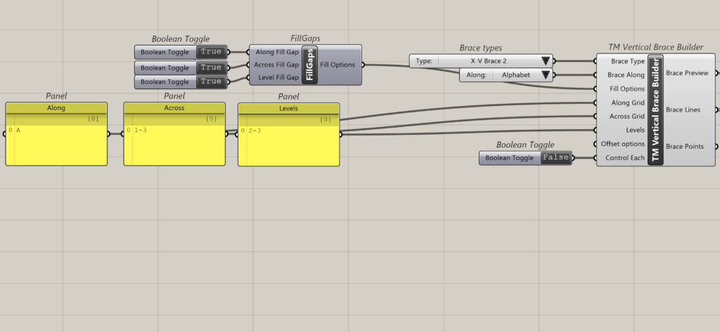
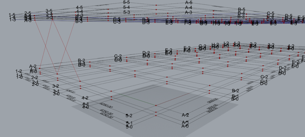
As shown above ‘X’ Braces have been modelled on Grid A.
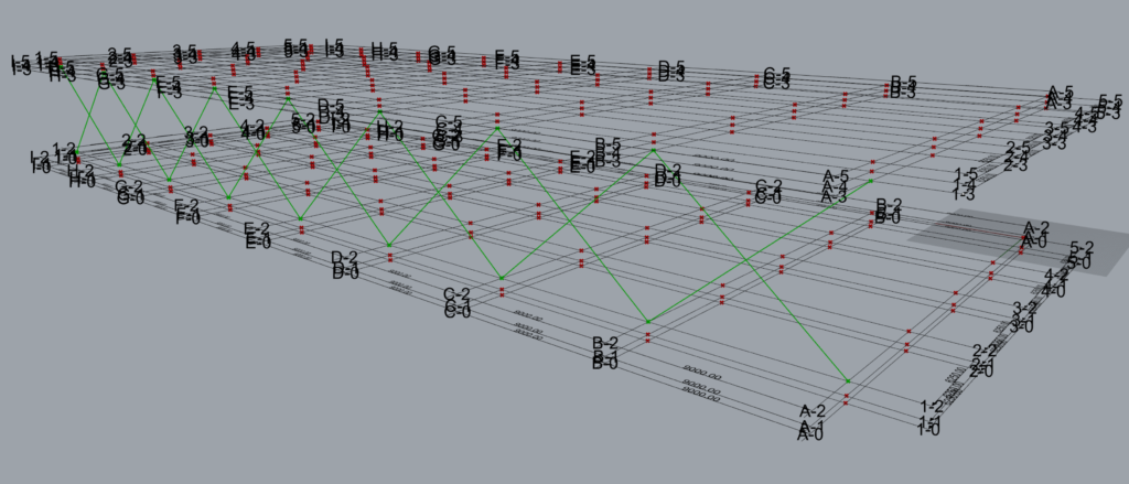
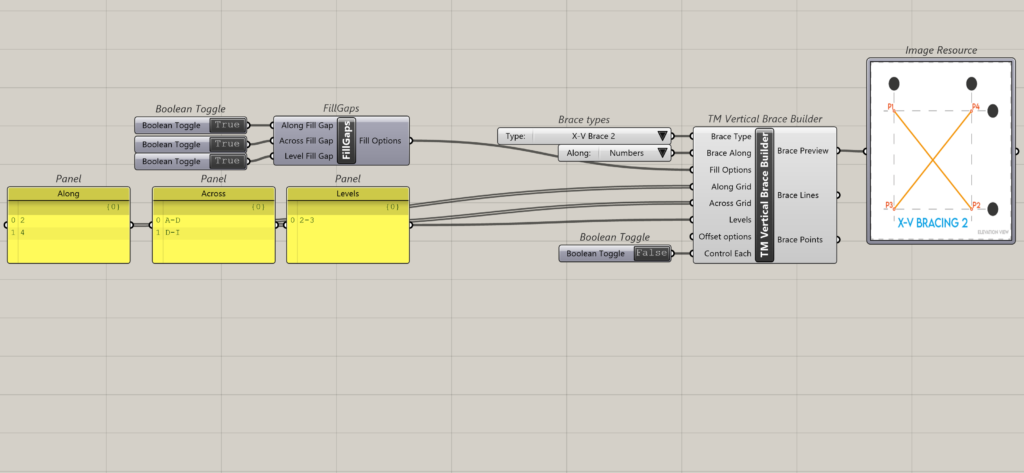
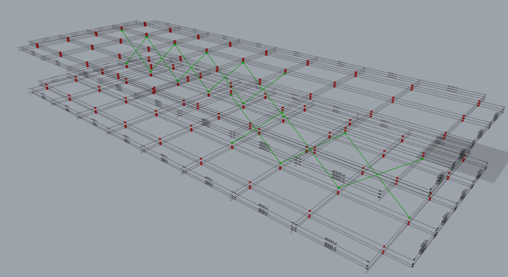
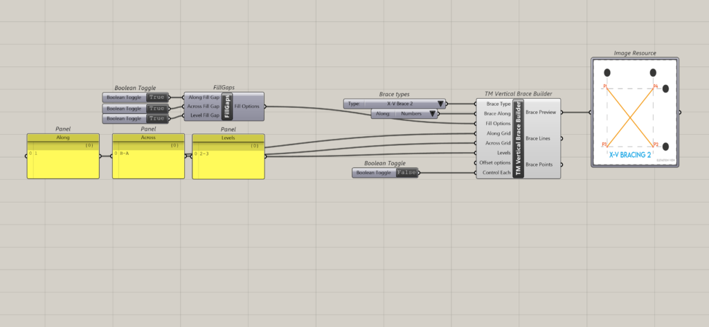
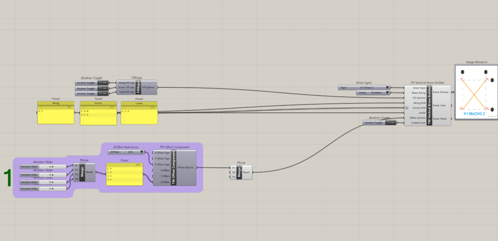
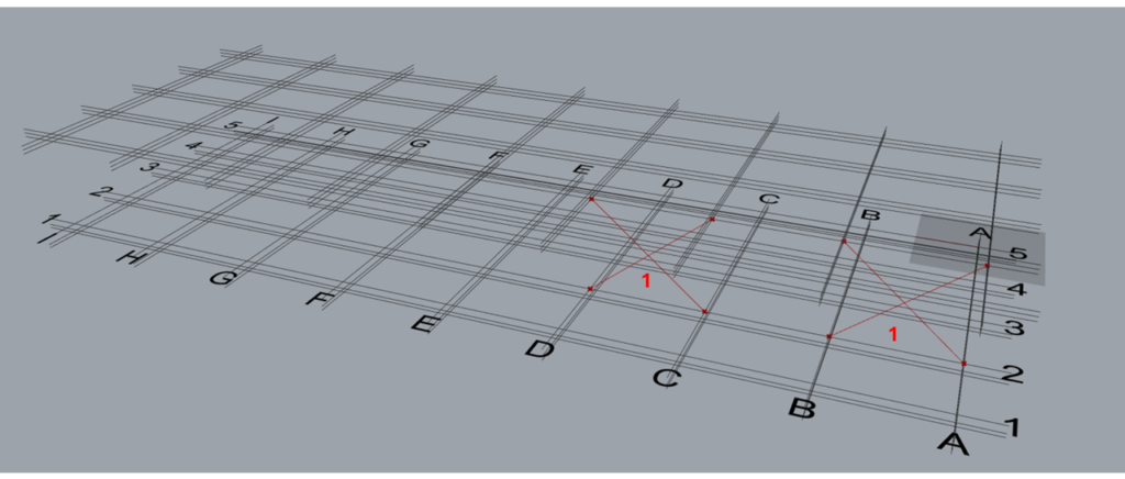
3.2 Number
When the brace along input is ‘Numbers’ then the braces shall be modelled along the alphabetical grid lines. Hence in the ‘Along Grid’ input only numbers shall be fed by the user.
As shown above x Braces have been modelled on Grid 1.
4 Heart of Builders
All the TM builder components have these three inputs which help in scaling different types of structural elements. They are
- Along Grid
- Across Grid
- Levels
‘Fill options’ is used to manipulate the way the grid information is read and used to model elements.
4.1 Along Grid
Takes the name of gridlines either-alphabets or numbers.
For some TM Builders components, it will take just a single entity (A/1) as an input while sometimes it will take a range (A-D/1-5) as an input.
4.2 Across Grid
Takes the name of gridlines either-alphabets or numbers in the form of a single entity (A/1) or as a range (A-D/1-5). If alphabets have been input in ‘Along’ then numbers shall be fed in ‘Across’ and vice versa.
4.3 Levels
Takes the level no. as input. For some elements it will take a range as well.
4.4 Fill Options
Fill options control the way how the structural elements are modelled picking up information from the gridlines.
The fill options affect inputs where grid lines ranges are used to model geometry. Using Booleans, it enables or disables users from using intermediate grid lines in a gridlines range to model structural elements.
The input takes a sub-component called ‘TM Fill Options’.
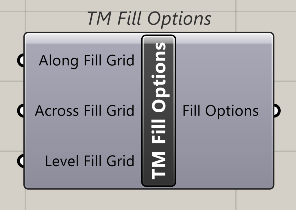
The sub-component essentially takes Booleans as input.
Please go through the ‘TM Vertical Brace Builder’ documentation and its case study to understand the inputs for this component better.
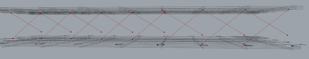
For e.g. if X type vertical braces are modelled along grid 1 and across A to C, using the ‘Across’ input in the TM Fill Option, the user can create geometry in two patterns.
- Across Fill Grid- True: Models three sets of braces between A-B, B-C & C-D.
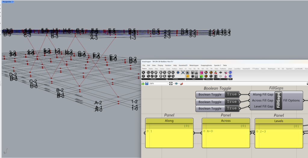
- Across Fill Grid-False: Models one set of Brace spanning from grid A to D directly.
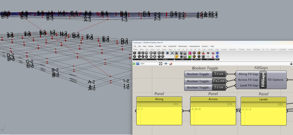
Hence it controls whether intermediate gridlines are used to create the structural elements or not.
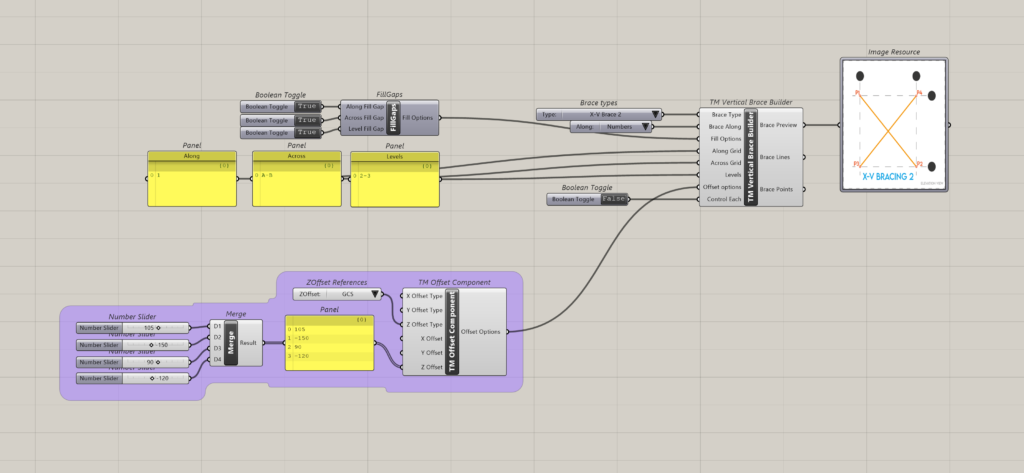
5 Offset- Other common required inputs- Offset
The TM Offset component helps to alter the location of the control points of geometries created using various TM modellers and builders.
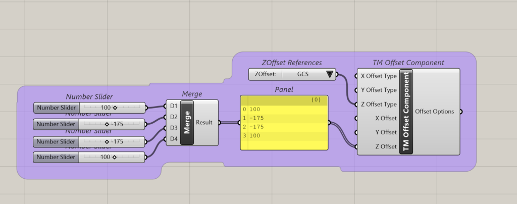
The no. of the inputs to this component depends on the no. of control points of the created geometry. More information can be found in ‘TM Offset’.
6 Data input format for the ‘heart’
As mentioned before, three inputs form the heart of the TM Builders community of components-Along, Across and Levels (A-A-L) inputs.
Some rules as well as multiple formats to feed the input to these parameters are explained here.
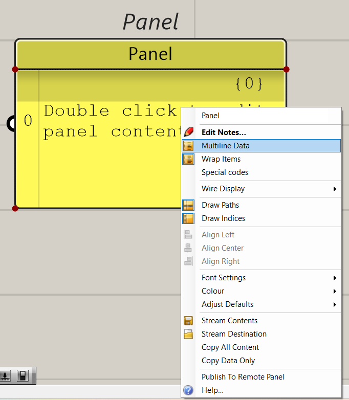
6.1 Disable ‘Multiline’ feature of panels
Panels are generally used to feed data to the A-A-L parameters. Disable multiline format of panels used to feed inputs to the mentioned parameters.
6.2 Allowed Formats for data entry
| Arrangement 1 | Arrangement 2 | Arrangement 3 | Arrangement 4 | Arrangement 5 | Arrangement 6 | Arrangement 7 | |
| Along | 2 | 2 | 3 | 3 | 3 | 1 | 1 |
| Across | 2 | 2 | 1 | 4 | 4 | 4 | 2 |
| Levels | 2 | 1 | 1 | 3 | 2 | 4 | 1 |
| Outcome | Works | Works | Doesn’t work | Doesn’t work | Doesn’t work | Works | Doesn’t work |
| Solution | Graft Along | Graft-Across | Graft-Across | ||||
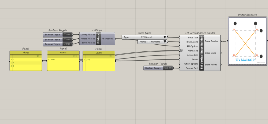
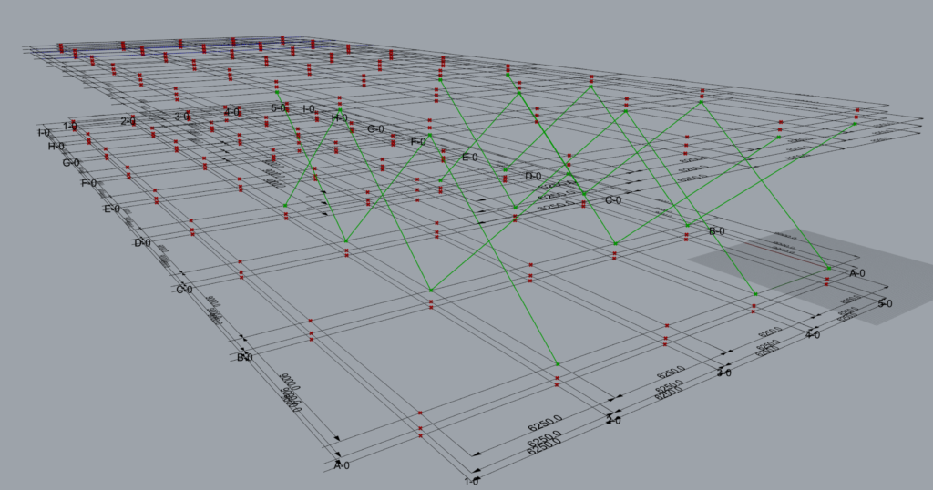
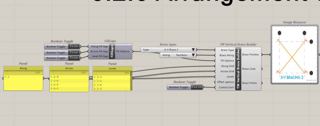
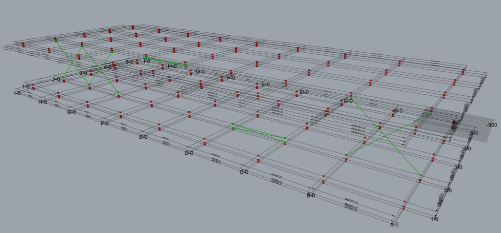
6.2.1 Arrangement 1
The data entry format where the list length of all the A-A-L inputs is 2-2-2 (equal) and works well with TM Builders components.
In all the component has modelled 8 sets of braces.
This is how the inputs are interpreted by the component.
| A-A-L | Input | Description |
| Along | 1 | This arrangement creates 3 sets of braces on grid 1 between levels 2 and 3. Set 1: Between grids A & B. Set 2: Between grids B & C Set 3: Between grids C & D |
| Across | A-D | |
| Level | 2-3 | |
| Along | 3 | This arrangement creates 4 sets of braces on grid 3 between levels 2 and 3. Set 1: Between grids D & E. Set 2: Between grids E & F. Set 3: Between grids G & H. Set 4: Between grids H & I. |
| Across | D-I | |
| Level | 2-3 |
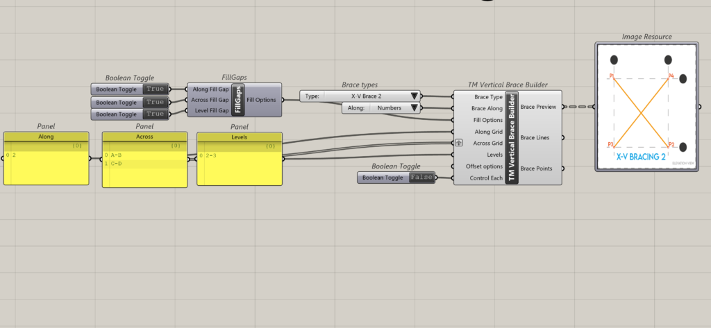
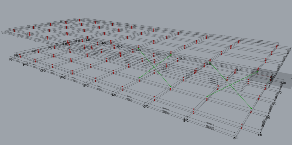
6.2.2 Arrangement 2
The data entry format where the A-A-L inputs length is 2-2-1 and works well with TM Builders without need for grafting.
In all the component has modelled 8 sets of braces.
This is how the inputs are interpreted by the component.
| A-A-L | Input | Description |
| Along | 2 | This arrangement creates 3 sets of braces on grid 2 between levels 2 and 3. Set 1: Between grids A & B. Set 2: Between grids B & C. Set 3: Between grids C & D. |
| Across | A-D | |
| Level | 2-3 | |
| Along | 4 | This arrangement creates 4 sets of braces on grid 4 between levels 2 and 3. Set 1: Between grids D & E. Set 2: Between grids E & F. Set 3: Between grids G & H. Set 4: Between grids H & I. |
| Across | D-I | |
| Level | 2-3 |
6.2.3 Arrangement 3
The data entry format where the A-A-L inputs length is 3-1-1 and works well with TM Builders when the longest list is grafted.
In all the component creates 8 sets of braces.
This is how the component interprets the above A-A-L input.
- Along: Grid 2; Across: A to D; Level: 2 to 3
- Along: Grid 4; Across: A to D; Level: 2 to 3
- Along: Grid 5; Across: A to D; Level: 2 to 3
The grouping of the geometry into various branches done by the component is provided below:
| Group | A-A-L | Input | Description |
| Group 1 | Along | 2,4,5 | This input creates 3 sets of braces on grid 2,4 and 5 in between grids A & B from levels 2 to 3. Set 1: Between grids A & B, on grid 2. Set 2: Between grids A & B, on grid 4. Set 3: Between grids A & B, on grid 5. |
| Across | A-B | ||
| Level | 2-3 | ||
| Group 2 | Along | 2,4,5 | This input creates 3 sets of braces on grid 2,4 & 5 in between grids B & C from levels 2 and 3. Set 1: Between grids B & C, on grid 2. Set 2: Between grids B & C, on grid 4. Set 3: Between grids B & C, on grid 5. |
| Across | B-C | ||
| Level | 2-3 | ||
| Group 3 | Along | 2,4,5 | This input creates 3 sets of braces on grid 2,4 & 5 in between grids C & D from levels 2 and 3. Set 1: Between grids C & D, on grid 2. Set 2: Between grids C & D, on grid 4. Set 3: Between grids C & D, on grid 5. |
| Across | C-D | ||
| Level | 2-3 |
Geometries created by the component where one or multiple entries have been grafted can be controlled only in clusters or groups and not individually.
Note: Also, the component ceases to maintain a unique branch for each brace. Hence the user is requested to use grafts only in situations such a grouping or clustering for offset control is desirable.
6.2.4 Arrangement 4
The data entry format where the A-A-L inputs length is 3-4-3 and works well with TM Builders when the longest list (Across) is grafted.
This is how the component interprets the above A-A-L input.
- Along: Grid 2; Across: A to B; Level: 2 to 3
- Along: Grid 2; Across: B to D; Level: 2 to 3
- Along: Grid 2; Across: E to G; Level: 2 to 3
- Along: Grid 2; Across: G to I; Level: 2 to 3
- Along: Grid 4; Across: A to B; Level: 1 to 2
- Along: Grid 4; Across: B to D; Level: 1 to 2
- Along: Grid 4; Across: E to G; Level: 1 to 2
- Along: Grid 4; Across: G to I; Level: 1 to 2
- Along: Grid 5; Across: A to B; Level: 2 to 3
- Along: Grid 5; Across: B to D; Level: 2 to 3
- Along: Grid 5; Across: E to G; Level: 2 to 3 Along: Grid 5; Across: G to I; Level: 2 to 3
The grouping of the geometry into various branches (total 6) done by the component is provided below:
Group |
A-A-L |
Input |
Description |
Group 1 |
Along |
2 |
This input creates 4 sets of braces on grid 2 between levels 2 and 3.
|
Across |
A-B B-C E-F G-H |
||
Level |
2-3 |
||
Group 2 |
Along |
2 |
This input creates 3 sets of braces on grid 2 between levels 2 and 3.
|
Across |
C-D F-G H-I |
||
Level |
2-3 |
||
Group 3 |
Along |
4 |
This input creates 4 sets of braces on grid 4 between levels 2 and 3.
|
Across |
A-B B-C E-F G-H |
||
Level |
1-2 |
||
Group 4 |
Along |
4 |
This input creates 3 sets of braces on grid 4 between levels 1 and 2.
|
Across |
C-D F-G H-I |
||
Level |
1-2 |
||
Group 5 |
Along |
5 |
This input creates 4 sets of braces on grid 5 between levels 2 and 3.
|
Across |
A-B B-C E-F G-H |
||
Level |
2-3 |
||
Group 6 |
Along |
5 |
This input creates 3 sets of braces on grid 5 between levels 2 and 3.
|
Across |
C-D F-G H-I |
||
Level |
2-3 |
Arrangement 4 Interpretation
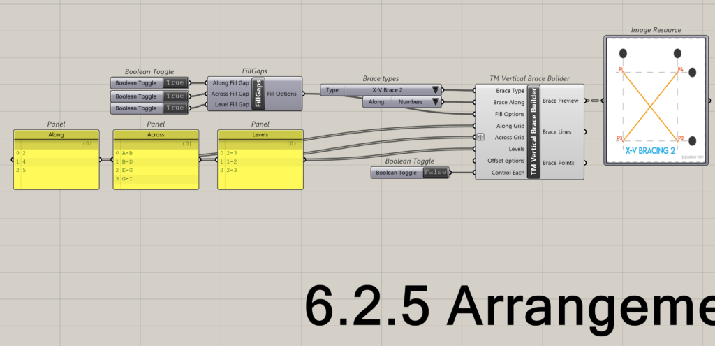
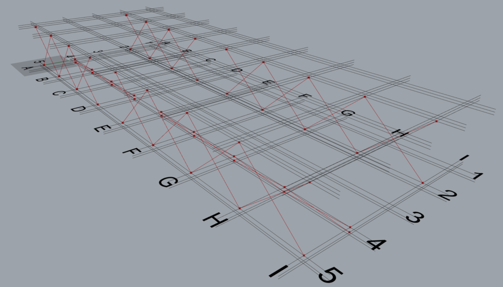
6.2.5 Arrangement 5
No solution possible for arrangement 5. Modellers are advised to avoid this type of input.
6.2.6 Arrangement 6
The data entry format where the A-A-L inputs length is 1-4-4 and works well with TM Builders without need for grafting.
This is how the component interprets the above A-A-L input.
- Along: Grid 2; Across: A to B; Level: 2 to 3
- Along: Grid 2; Across: C to D; Level: 1 to 2
- Along: Grid 2; Across: E to F; Level: 3 to 4
- Along: Grid 2; Across: G to I; Level: 2 to 3
The grouping of the geometry into various branches (total 5) done by the component is provided below:
Group |
A-A-L |
Input |
Description |
Group 1 |
Along |
2 |
This input creates 1 set of brace, on grid 2 between levels 2 and 3.
|
Across |
A-B |
||
Level |
2-3 |
||
Group 2 |
Along |
2 |
This input creates 1 set of brace, on grid 2 between levels 1 and 2.
|
Across |
C-D |
||
Level |
2-3 |
||
Group 3 |
Along |
2 |
This input creates 1 set of brace, on grid 2 between levels 3 and 4.
|
Across |
E-F |
||
Level |
3-4 |
||
Group 4 |
Along |
2 |
This input creates 1 set of brace, on grid 2 between levels 2 and 3.
|
Across |
G-H |
||
Level |
2-3 |
||
Group 5 |
Along |
2 |
This input creates 1 set of brace, on grid 2 between levels 2 and 3.
|
Across |
H-I |
||
Level |
2-3 |
Arrangement 6 Interpretation
6.2.7 Arrangement 7
The data entry format where the A-A-L inputs length is 1-2-1 and works well with TM Builders with the Across input grafted.
This is how the component interprets the above A-A-L input.
- Along: Grid 2; Across: A to B; Level: 2 to 3.
- Along: Grid 2; Across: C to D; Level: 2-3.
The grouping of the geometry into various branches (total 5) done by the component is provided below:
Group |
A-A-L |
Input |
Description |
Group 1 |
Along |
2 |
This input creates 2 set of braces, on grid 2 between levels 2 and 3.
|
Across |
A-B C-D |
||
Level |
2-3 |
7 Brace points order
One can identify the brace type using the brace preview window.
But how are the nodes order decided while modelling using the A-A-L logic is explained below.
7.1 Example 1
Let’s consider a single set of brace modelled on grid 1 between grids A and B and between levels 2 & 3 using the following input.
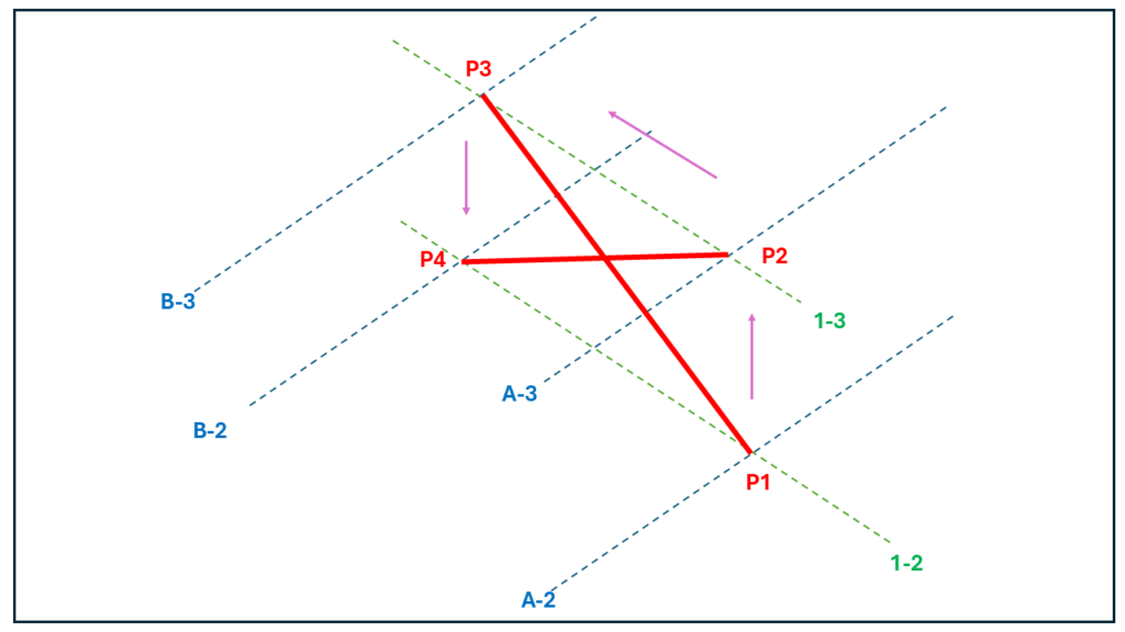
As the brace is on grid 1 and between grid A and B, the start point of brace P1 lies at the intersection of grids 1 & A at level 2. The second point of the brace P2 lies at the intersection of grid lines 1 and A at level 3. The third point P3 lies at the intersection of gridlines B & 1 at level 3 while P4 lies at the intersection of the same gridlines but at level 2.
One may notice that the order of entries in the ‘Along’ input governs the order in which the braces are modelled.
7.2 Example 2

8 Using control each
Using control each feature, one can control the offsets of entire brace sets or a single brace set if required, although it also depends on how A-A-L inputs have been fed.
The X Brace used in the study has 4 nodes whose locations in the 3D space can be altered using the TM Offset component.
Although the same philosophy shall be valid for almost all geometry creating TM Builder and modeller components. The arrangements discussed in section 6.2 shall be used to demonstrate this feature as well.
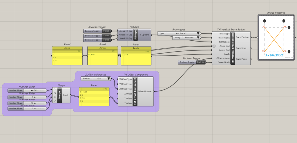
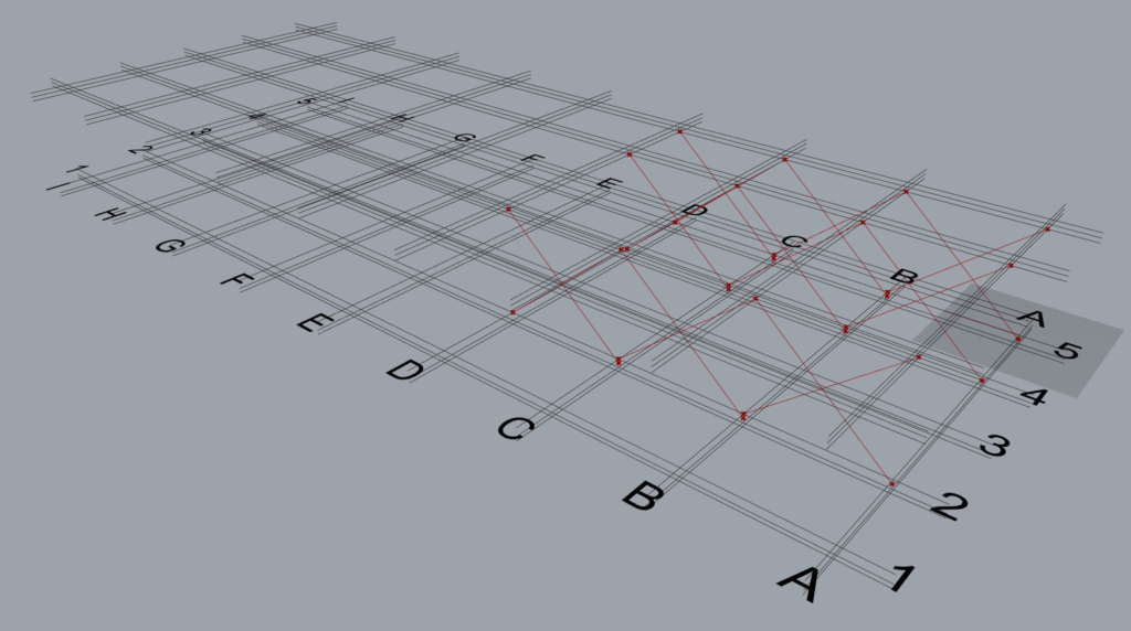
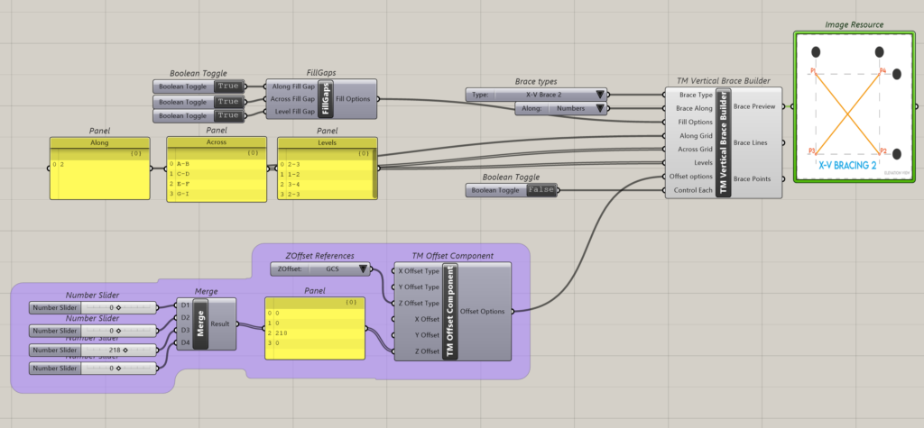
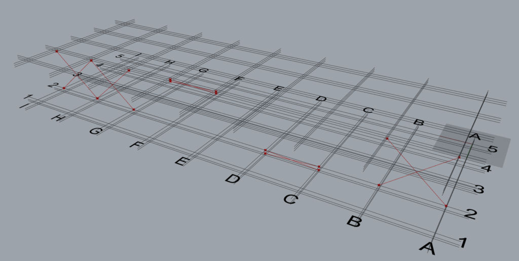
8.1 Arrangement 1
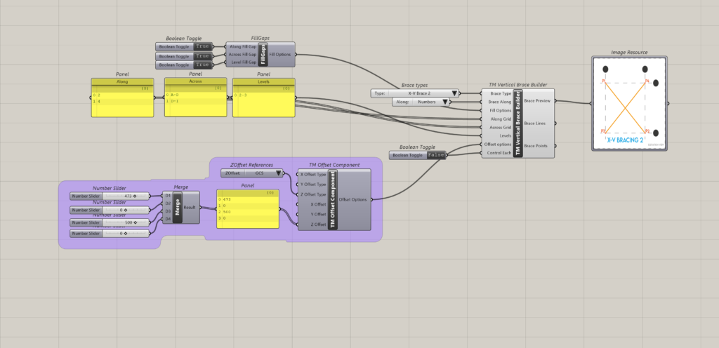
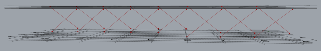
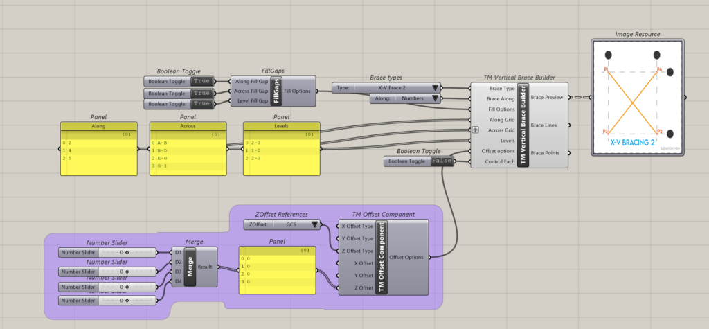
8.1.1 Control each is ‘False’
It can be seen that one ‘TM Offset’ component controls the offsets for all sets of braces.
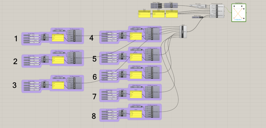
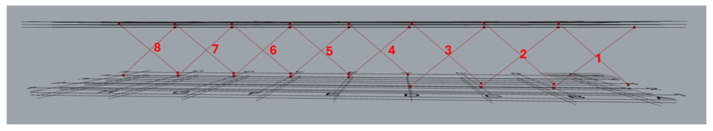
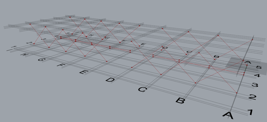
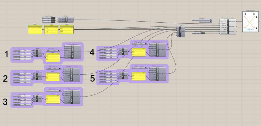
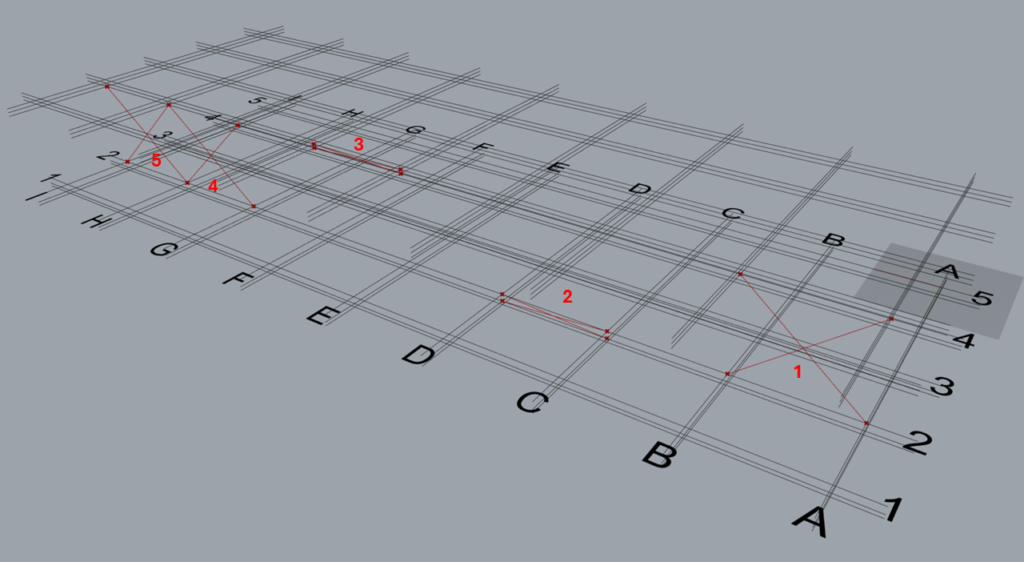
8.1.2 Control each is ‘True’

It can be seen that eight ‘TM Offset’ component control the offsets for 8 sets of braces respectively.
8.2 Arrangement 2
8.2.1 Control each is ‘False’
8.2.2 Control each is ‘True’
It can be seen that eight ‘TM Offset’ component control the offsets for 8 sets of braces respectively i.e. each brace offset can be controlled individually.
8.3 Arrangement 3
8.3.1 Control each is ‘False’
8.3.2 Control each is ‘True’
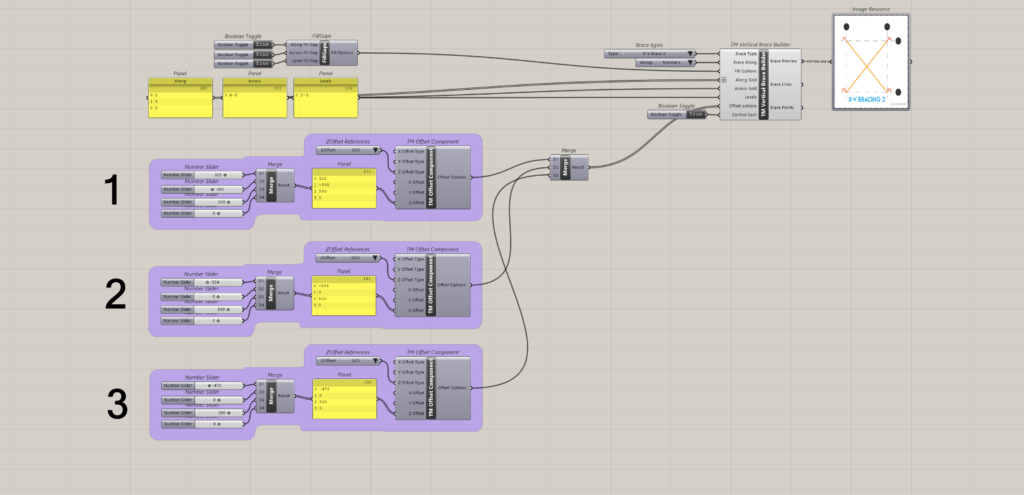
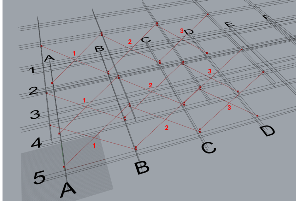
As shown, three TM Offset components are required to control 9 braces.
- First offset component controls three sets of braces that are modelled between grids A & B, along grids 2,4 & 5.
- Second offset component controls three sets of braces that are modelled between grids B & C.
- Third offset component controls three sets of braces that are modelled between grids C & D.
Note: Individual control of each brace set is not possible for this arrangement.
8.4 Arrangement 4
8.4.1 Control Each is ‘False’
It can be seen that one ‘TM Offset’ controls all the braces created by the component.
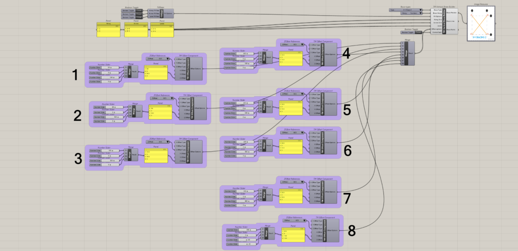
8.4.2 Control Each is ‘True’
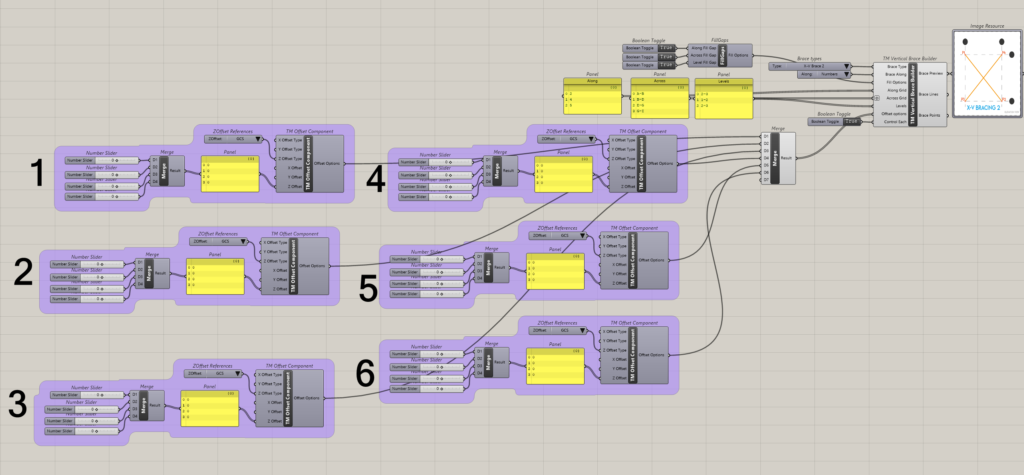
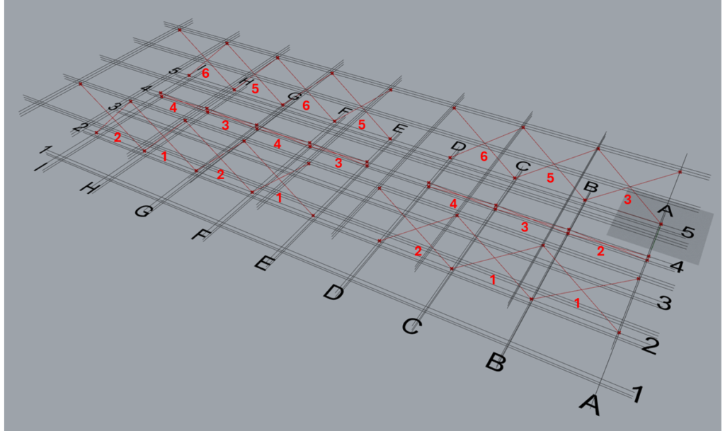
It can be seen that 6 ‘TM Control Offsets’ are required to alter the offsets of 21 sets of braces.
TM Offset Component ID |
Brace Configuration Controlled |
1 |
|
2 |
|
3 |
|
4 |
|
5 |
|
6 |
|
8.5 Arrangement 5
Not applicable.
8.6 Arrangement 6
8.6.1 Control Each is ‘False’
It can be seen that one ‘TM Offset’ controls all the braces created by the component.
8.6.2 Control Each is ‘True’
It can be seen that 5 ‘TM Control Offsets’ are required to alter the offsets of 5 sets of braces, maintaining a 1:1 relationship.
8.7 Arrangement 7
8.7.1 Control Each is ‘False’
It can be seen that one ‘TM Offset’ controls all the braces created by the component.
8.7.2 Control Each is ‘True’
It can be seen that 1 ‘TM Control Offsets’ is required to alter the offsets of 2 sets of braces.
Individual control of braces is not possible in this arrangement.