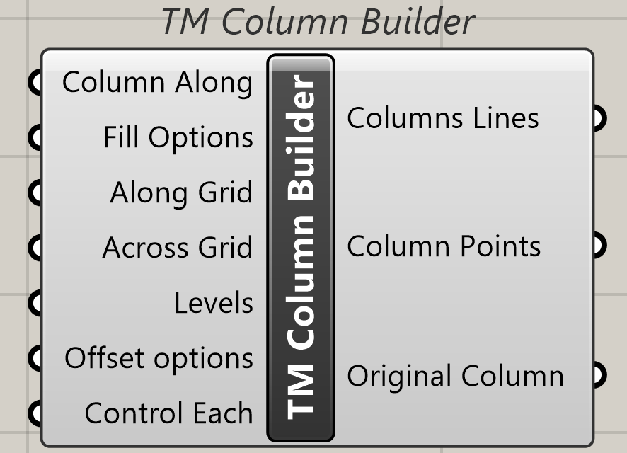
1 Component description
TM column is a grasshopper component that helps modelling 1D lines that can be used to model columns in Rhino with ease.
Grids (with names defined in a particular manner) are needed for the component to work. One can create such grids using the ‘TM Grid builder’ component.
1.1 Inputs
The user is requested to read the ‘How do TM Builders work’ documentation for a deeper understanding of the working of the various inputs.
1.1.1 Column Along
Attach a value list to generate the following options.
- Alphabet- Choose this if you want to generate columns along grids that have ‘alphabetical’ names.
- Number- choose this if you want to generate columns along grids that have ‘numeric’ names.
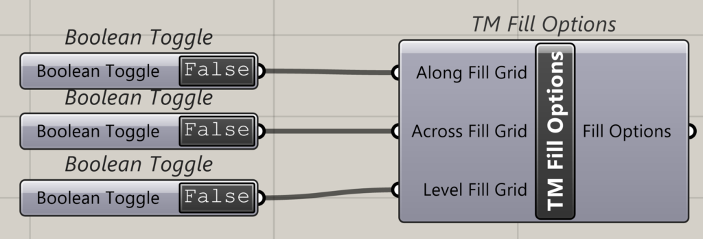
1.1.2 Fill Options
Takes a component called ‘TM Fill Gaps’ .
Helps in controlling if intermediate gridlines in between the chosen grid range are to be used for modelling the columns.
1.1.3 Along Grid
Takes the name of gridlines either-Alphabets or numbers. The grasshopper component ‘Panel’ may be used for the same.
Takes the name of gridlines either-alphabets or numbers in the form of a single entity (A/1) or as a range (A-D/1-5). If alphabets have been input in ‘Along’ then numbers shall be fed in ‘Across’ and vice versa.
1.1.4 Across
Takes the name of gridlines either-alphabets or numbers. The grasshopper component ‘Panel’ may be used for the same.
Takes the name of gridlines either-alphabets or numbers in the form of a single entity (A/1) or as a range (A-D/1-5). If alphabets have been input in ‘Along’ then numbers shall be fed in ‘Across’ and vice versa.
1.1.5 Levels
Takes a range (0-3) of levels.
1.1.6 Offset Options
Takes a component called ‘TM Offset component’. User can alter the location of end points of generated column lines using this component.
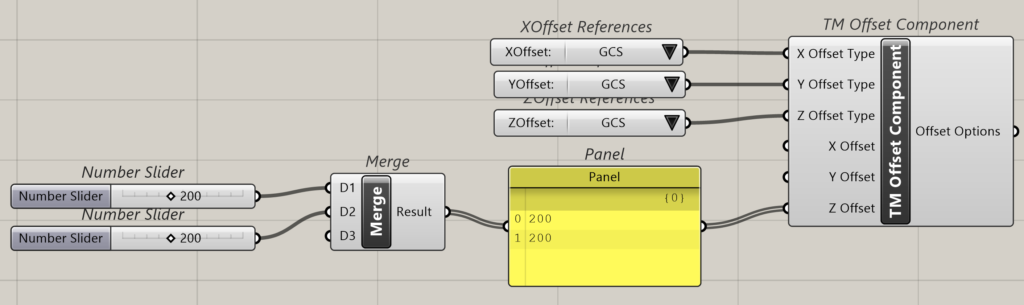
User can attach multiple ‘TM Offset Component’s too when ‘control each’ Boolean is true.
1.1.7 Control Each
Takes a Boolean toggle with the following outcomes.
- True– enables individual control of the offset of the columns.
- False– Disables individual control of the offset of the columns. Offsets of all the outputs are controlled as a group.
1.2 Output
1.2.1 Column Lines
Outputs the column lines generated by the component.
1.2.2 Column Points
Outputs the end points of the column lines generated by the component.
1.2.3 Original Column
Outputs the original column lines generated by the component without the offsets created by the user if any.
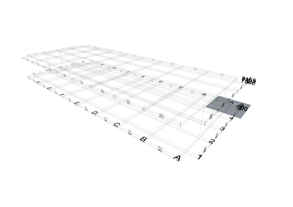
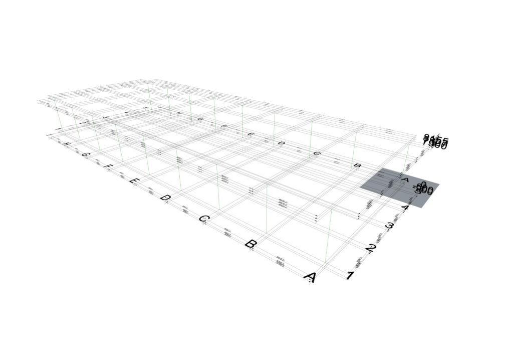
2 Case study- Portal Frame warehouse
This section describes the various ways in which the columns of the portal frame warehouse can be generated easily.
Image of portal frame warehouse 3D pic
The user is requested to first read the documentation on this case study- ‘Steel Warehouse’.
As shown in the pic the user needs to model columns on the following grid intersections.
Sr. No. |
Grid Intersection |
Level |
1 |
A1 |
2 to 3 |
2 |
B1 |
2 to 3 |
3 |
C1 |
2 to 3 |
4 |
D1 |
2 to 3 |
5 |
E1 |
2 to 3 |
6 |
F1 |
2 to 3 |
7 |
G1 |
2 to 3 |
8 |
H1 |
2 to 3 |
9 |
I1 |
2 to 3 |
10 |
A2 |
2 to 4 (Undivided) |
11 |
A3 |
2 to 5 (undivided) |
12 |
A4 |
2 to 4 (Undivided) |
13 |
I2 |
2 to 4 (Undivided) |
14 |
I3 |
2 to 5 (undivided) |
15 |
I4 |
2 to 4 (Undivided) |
16 |
A5 |
2 to 3 |
17 |
B5 |
2 to 3 |
18 |
C5 |
2 to 3 |
19 |
D5 |
2 to 3 |
20 |
E5 |
2 to 3 |
21 |
F5 |
2 to 3 |
22 |
G5 |
2 to 3 |
23 |
H5 |
2 to 3 |
24 |
I5 |
2 to 3 |
Table 1: Column line location and extents
Multiple options have been presented below showcasing the varied ways in which these column lines can be modelled.
The user is requested to pay attention to the ‘TM Fill Gaps’ Boolean status and how they have been used to manipulate geometry creation.
More information on ‘TM Fill Options’ can be found on the page ‘How do TM Builder work’.
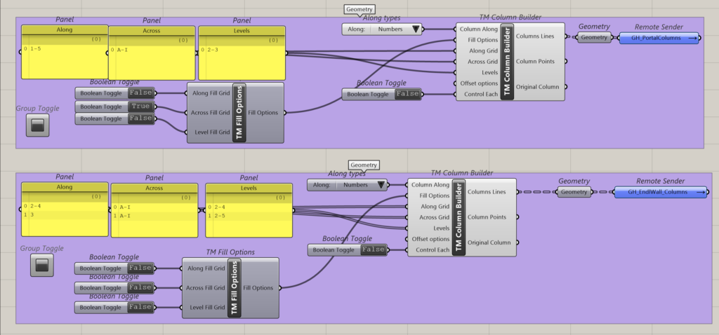
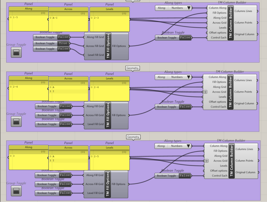
2.1 Option 1
Two instances of the component have been used to create the required columns.
- Component 1: This definition creates column lines along 1 & 5 across grids A to I between levels 2 and 3. A total of 18 column lines have been modelled.
- Component 2: This definition has two rows of inputs. A total of 6 column lines have been modelled.
- Input 1 creates column lines along grids 2 & 4 on grids A & I between levels 2 & 4.
- Input2 creates column lines along gird 3 on grids A & I between levels 2 & 5.

2.2 Option 2
Three instances of the component have been used to create the required columns.
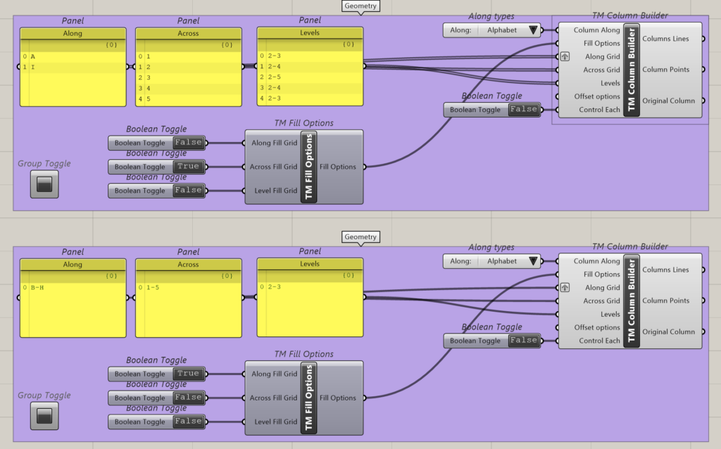
- Component 1: This definition creates column lines along grid B to H across grids 1 & 5 between levels 2 and 3. In total it models 14 column lines.
- Component 2: This definition has two rows of inputs and models 4 column lines in total.
- Input 1 creates column lines along grid A and across grids 1 and 5 between levels 2 and 3.
- Input 2 creates column lines along grid I and across grids 1 and 5 between levels 2 and 3.
- Component 3: This definition has three rows of inputs and models 6 column lines in total.
- Input 1 creates column lines along grid 2 across grid A & I between levels 2 & 4.
- Input 2 creates column lines along grid 3 across grids A & I between levels 2 & 5.
- Input3 creates column lines along grid 4 across grids A & I between levels 2 & 4.
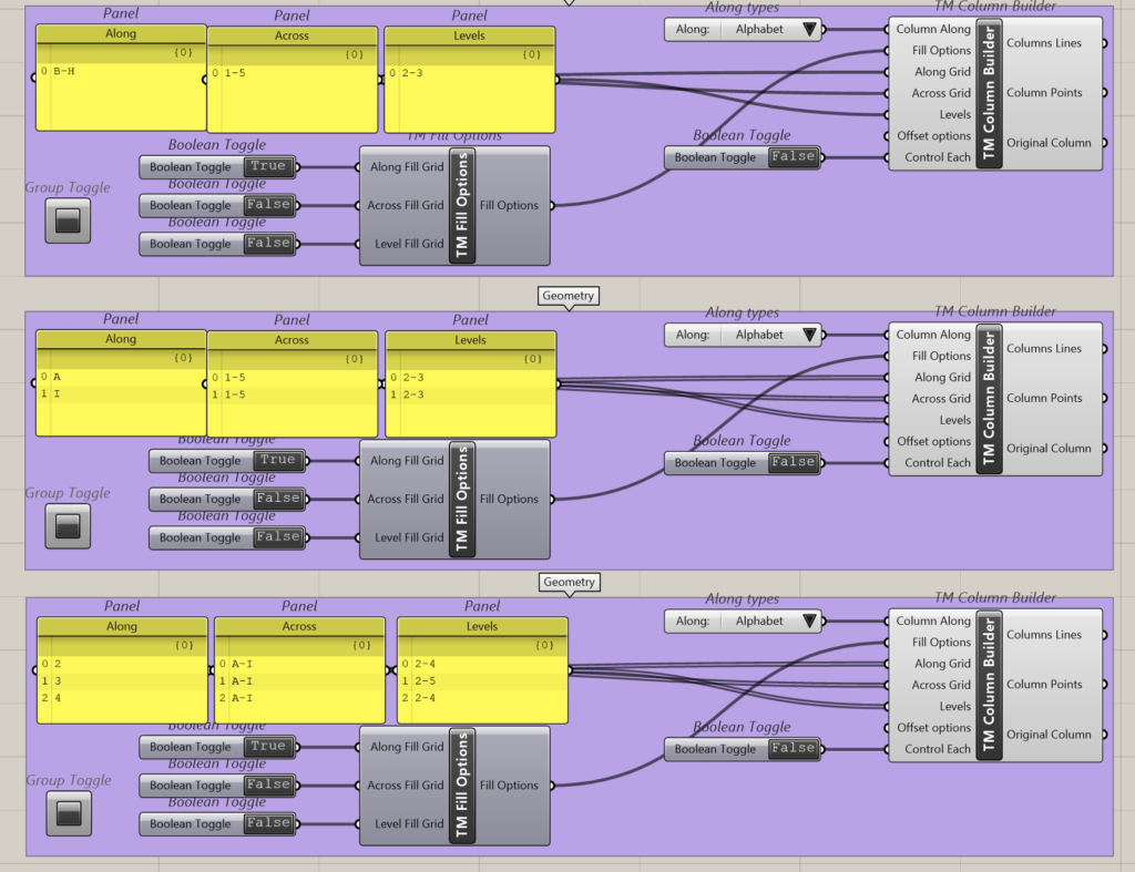
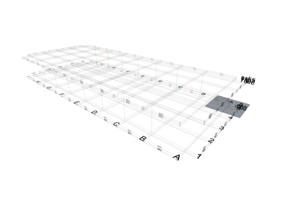


2.3 Option 3
Three instances of the component have been used to create the required columns.
- Component 1: This definition creates column lines along 1 & 5 across grids A to I between levels 2 and 3. A total of 18 column lines have been modelled.
- Component 2: As one of the inputs is grafted, it can be considered that there are two rows of input and creates 4 column lines in total.
- Input 1 creates column lines along grids 2 & 4, across grid A between levels 2 & 4.
- Input 2 creates column lines along grids 2 & 4, across grid A between levels 2 & 4.
- Component 3: As one of the inputs is grafted, it can be considered that there are two rows of input and creates 2 column lines in total.
- Input 1 creates column lines along grids 3, across grid A between levels 2 & 5.
- Input2 creates column lines along grids 3, across grid I between levels 2 & 5.


2.4 Option 4
Two instances of the component has been used to create the required columns.
- Component 1- As one of the inputs is grafted, it can be considered that there are ten rows of input and creates 10 column lines in total.
- (A-A-L: A-1-2 to 3) Input 1 creates column line along grid A across grid 1 between levels 2 & 3.
- (A-A-L: A-2-2 to 4) Input 2 creates column line along grid A across grid 2 between levels 2 & 4.
- (A-A-L: A-2-3 to 5) Input 3 creates column line along grid A across grid 3 between levels 2 & 5.
- (A-A-L: A-4-2 to 4) Input 4 creates column line along grid A across grid 4 between levels 2 & 4.
- (A-A-L: A-5-2 to 3) Input 5 creates column line along grid A across grid 5 between levels 2 & 3.
- (A-A-L: I-1-2 to 3) Input 6 creates column line along grid I across grid 1 between levels 2 & 3.
- (A-A-L: I-2-2 to 4) Input 7 creates column line along grid I across grid 2 between levels 2 & 4.
- (A-A-L: I-2-3 to 5) Input 8 creates column line along grid I across grid 3 between levels 2 & 5.
- (A-A-L: I-4-2 to 4) Input 9 creates column line along grid I across grid 4 between levels 2 & 4.
- Component 2- This definition creates column lines along B & H across grids 1to 5 between levels 2 and 3. A total of 14 column lines have been modelled.