TM Grid Builders are a set of components that help build grids in Rhino with ease. They also apply a specific nomenclature to the grid lines that help the ‘TM Builder’ components to easily identify them.
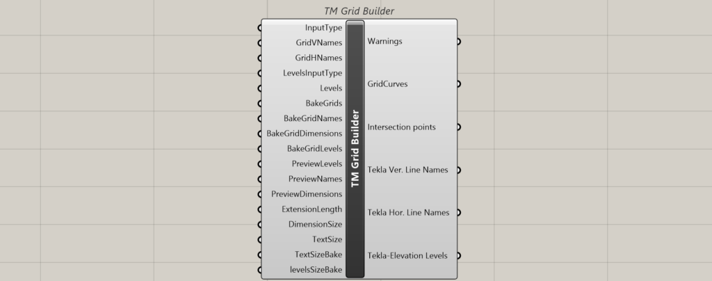
This component not only help creates girds but also translate it to user specified elevations for creating elements using other builder components.
Inputs
Input Type
Attach a value list to generate the following options:
- Automatic: This option enables the user to model the grid lines using their starting and ending points in X,Y format.
- Referenced: This option enables the user to reference already existing lines in Rhino and use this component to assign them names based on the logic defined below. The user can use this option when the grid lines are already drawn in Rhino manually or created using vanilla grasshopper. The user doesn’t have to name the lines, the component will do it for the user.
Grid Names
The component primarily divides the grid lines into two categories based on their orientation in the Rhino (plan) view:
- Vertical-Lines that appear vertical in Rhino (plan) view.
- Horizontal-Lines that appear horizontal in Rhino (plan) view.
GridVNames
Takes alphabetical letters/numbers to be assigned to the vertical lines. If alphabetical letters are assigned to vertical lines then make sure to assign numbers to horizontal lines and vice versa.
Default names are assigned if nothing is provided.
If the alphabetical names/ numbers are not in sequential order then the TM builders might not work properly.
They can be entered in the reverse order as well, which will work as long as the order is sequential.

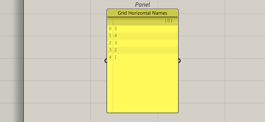
GridHNames
Takes alphabetical letters/numbers to be assigned to the Horizontal lines. If alphabetical letters are assigned to horizontal lines then make sure to assign numbers to vertical lines and vice versa.
Default names are assigned if nothing is provided.
If the alphabetical letters/numbers are not in sequential order then the TM builders might not work properly. They can be entered in the reverse order as well, which will work as long as the order is sequential.
Levels Input Type
Attach a value list to populate the following options:
- Elevation Cumulative: Input grid level spacing as cumulative values, excluding 0 level (with grids below 0 in negative).
- Elevation Spacing: Input grid level spacing from top to bottom, excluding 0 level (with grids below 0 in negative).
Levels
Takes a list of numbers indicating the important elevations of the structure where one requires to model geometry. As explained before, elevations can be entered in two formats.
The grid at level zero shall automatically be created by the component, and the user is strictly not to mention that elevation while feeding level.
The elevation levels shall be mentioned in the order of the top most elevation to the bottom most elevation Let’s say, we want to our grids to be repeated at following elevations:
- 0
- 3500.00
- 7000.00
- 8500.00
- 10,000.00
To represent the above elevations. one shall enter them in the following format.
Elevation Cumulative
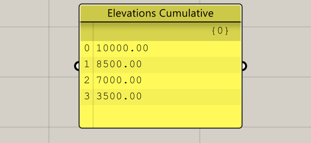
If elevations below ground level are required then the elevations shall be entered in a negative format. For e,g, gridlines at 300mm below zero shall be entered as ‘-300’.
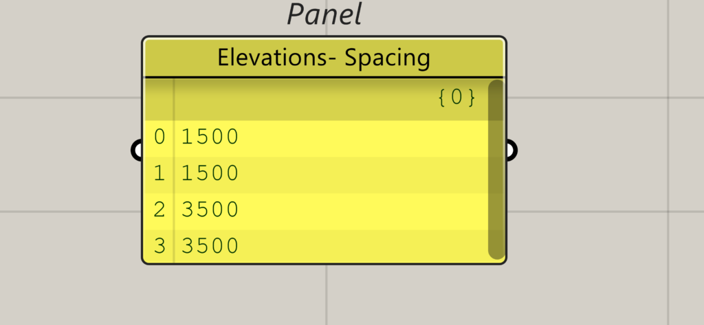
Elevation Spacing
Elevation spacings corresponding to the above elevations shall be calculated as follows:
- 10000-8500=1500mm
- 8500-7000=1500mm
- 7000-3500=3500mm
- 3500-0=3500mm
Bake Grids
Takes a button which when pressed bakes the grid lines to Rhino.
Bake Grid Names
Takes a button which when pressed bakes the names assigned to the grid lines to Rhino.
Bake Grid Dimensions
Takes a button which when pressed bakes the inter-gridlines spacings to Rhino.
Bake Grid Levels
Takes a button which when pressed bakes the grid elevations.
Bake Grid Levels
Takes a button which when pressed bakes the grid elevations.
Preview Levels
Takes a Boolean toggle that allows to preview the elevations. Takes as many toggles as the number of elevations thus assigning individual control over each elevation.
Preview Names
Takes a Boolean toggle that controls the visibility of gridlines’ names in Rhino window. Takes as many toggles as the number of elevations thus assigning individual control over each elevation.
Preview Dimensions
Takes a Boolean toggle that controls the visibility of the gridline spacings in Rhino. Takes as many toggles as the number of elevations thus assigning individual control over each elevation.
Extension Length
Takes a number which then extends the gridline by the mentioned length on either side.
Dimension Size
Takes a number that controls the font size of the gridlines spacing dimensions text.
Text Size
Takes a number that controls the font display text size of the gridlines labels.
Text Size Bake
Takes a number that controls the baked font display text size of the gridlines labels.
Vertical and Horizontal lines- start point and end points
The following inputs are dynamically generated when the input type chosen is ‘Automatic’.
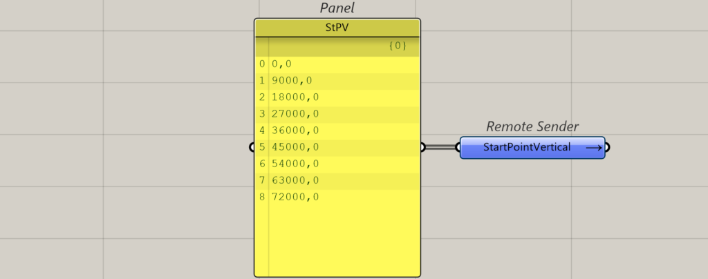
Start Point -Ver. line
Takes x,y coordinate inputs that help locate the start point of the vertical grid lines (in Rhino XY plane).
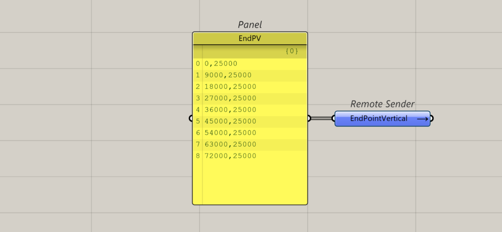
End Point-Ver. Line
Takes x,y coordinate inputs that help locate the end point of the vertical grid lines (in Rhino XY plane).
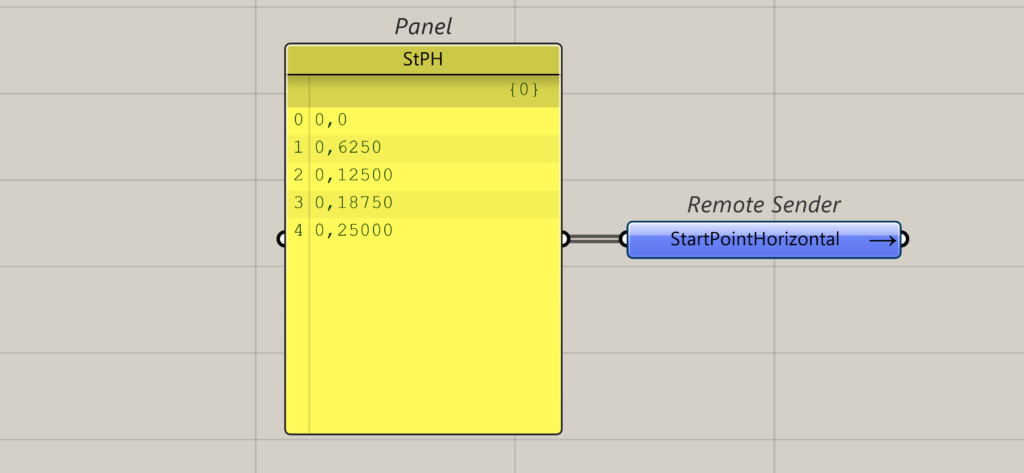
Start Point-Hor. Line
Takes x,y coordinate inputs that help locate the start point of the Horizontal grid lines (in Rhino XY plane).
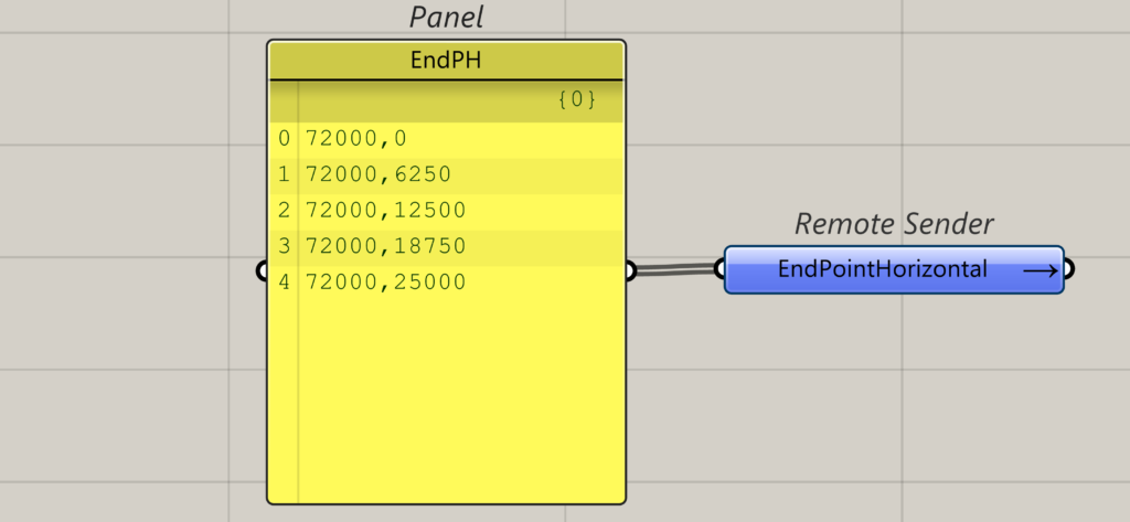
End Point-Hor. Line
Takes x,y coordinate inputs that help locate the end point of the Horizontal grid lines (in Rhino XY plane).
Reference Vertical and Horizontal Lines
The following inputs are dynamically generated when the input type chosen is ‘Referenced’.
RefVLines
Input the vertical lines (Rhino XY) modelled in Rhino manually with their end points at Rhino Z= 0, and imported into grasshopper.
It isn’t compulsory for the lines to be exactly vertical, inclined lines (in the XY plane) can also be fed. The order in which they are imported is the order that shall be used to assign them labels by the component.
RefHLines
Input the horizontal lines (Rhino XY) modelled in Rhino manually with their end points at Rhino Z= 0, and imported into grasshopper.
It isn’t compulsory for the lines to be exactly vertical, inclined lines (in the XY plane) can also be fed. The order in which they are imported is the order that shall be used to assign them labels by the component.
Outputs
Warnings
Attach a panel to read the warnings issued by the component.
Grid Curves
Outputs the gridlines generated by the component in a tree format.
Intersection Points
Outputs the points generated at the intersection of the horizontal and vertical grid lines.
Tekla Ver. Names
Outputs the ‘GridVNames’ in desired Tekla format.
Tekla Hor. Names
Outputs the ‘GridHNames’ in desired Tekla format.
Tekla-Elevation Levels
Outputs the elevation levels texts in desired Tekla format.
Bug
- When the gridlines are inclined, the dimension lines indicating the inter grid distances are not accurately calculated.
Later revisions shall address these issues.