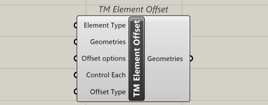
The element offset component helps in editing the location of the end points of the existing lines modelled using other builders, modellers or native grasshopper components. In other words, it helps in tweaking the work points of line elements.
There might be a situation where the work point for the analytical model shall be different from the workpoint for the fabrication model. This helps in altering the work points of the Lines representing braces, beams, etc. in software like Tekla Structures.
Inputs
Element Type
Takes a value list and auto-populates the options.
- Curve elements- The geometries input then accepts the line elements as the inputs.
Geometries
Takes a list or a tree of geometries in this case lines/curves with 2 or more control points.
Offset Options
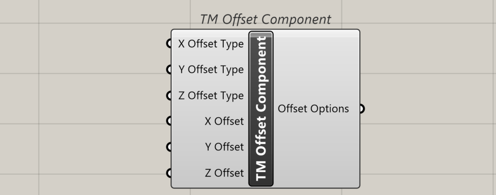
Takes a TM offset component or a list of it. This component enables offsetting the end point of the lines.
Inputs
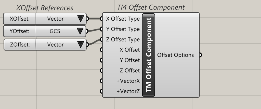
X Offset-Type
Takes a value list in which the following options are created dynamically.
- GCS-Follows the Rhino X axis
- Local grid-Not applicable.
- Vector-Allows the user to feed a vector to the component along which the offset happens.
X Offset
Takes the distances (as numbers) by which the end points are offset.
For line elements, takes two numbers which are the distances by which the end points are offset.
If X offset type is GCS, then the end points are offset in the Rhino X direction. If the X Offset type is Vector then an additional dynamic input-Vector X is created in which the vector can be fed.
Y offset
Takes the distances (as numbers) by which the end points are offset.
For line elements, takes two numbers which are the distances by which the end points are offset.
If Y offset type is GCS, then the end points are offset in the Rhino Y direction. If the Y Offset type is Vector then an additional dynamic input-Vector Y is created in which the vector can be fed.
Z Offset
Takes the distances (as numbers) by which the end points are offset.
For line elements, takes two numbers which are the distances by which the end points are offset.
If Z offset type is GCS, then the end points are offset in the Rhino Y direction. If the Z Offset type is Vector then an additional dynamic input-Vector Z is created in which the vector can be fed.
Output
Offsets
Connect this output to the ‘offset’ input of the TM element offset component.
Control Each
Takes a Boolean.
- True- gives ability to offset each geometry item individually by attaching multiple TM offset components.
- False-one TM offset component controls the offsets of all the included geometries.
Offset Type
Attach a value list to dynamically generate the following options:
- General Offset
- Branch Offset
General offset works better when the geometry input is a list, while branch offset works better when the geometry input is in the form of a data tree. This is a suggestion and not a rule, both patterns work with both type of inputs, the user is requested to test both of them while using the component and select the one that suits his workflow the best. A demonstration is given below for the both the patterns with multiple combinations.
Output
Geometries
Outputs the new geometries with the updated offsets.
Downstream use
Can be used to change the workpoints of the curves that create items like beams, columns, braces etc. in Tekla structures.