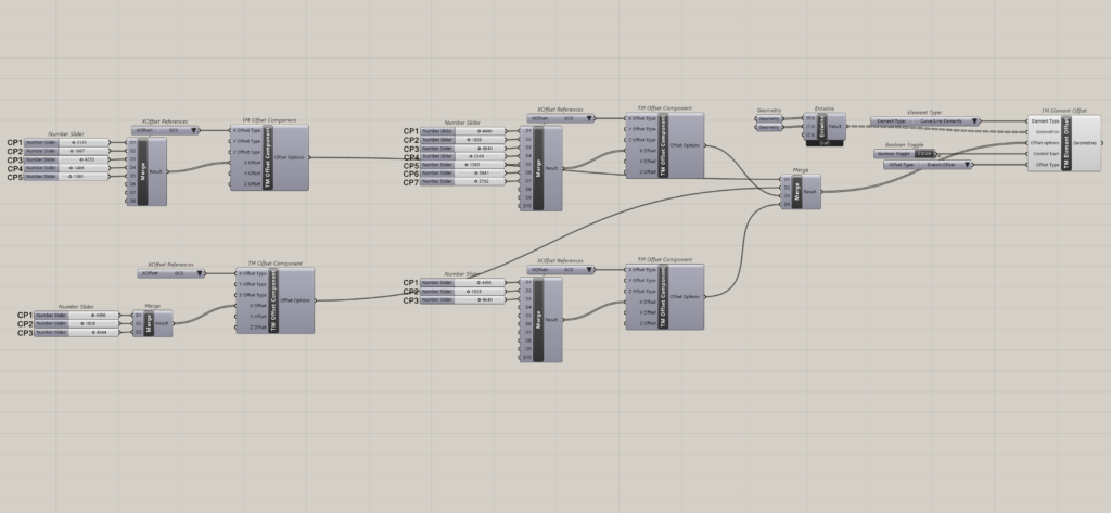
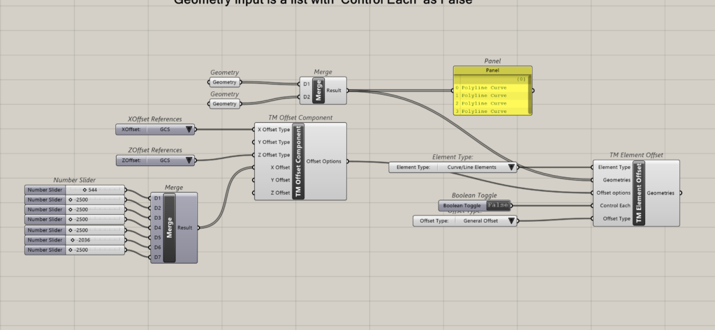
Demo using ‘General Offset’ setting for lines with two control points i.e. only end points
As each line contains two end points, two offset values need to be provided, otherwise the component wont work.
‘TM Offset’ is required for the ‘TM Element Offset’ to work properly.
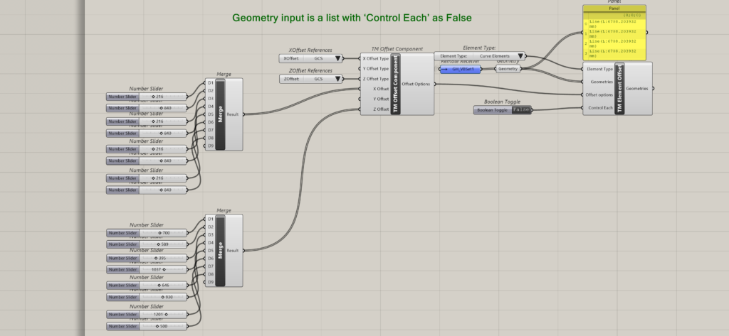
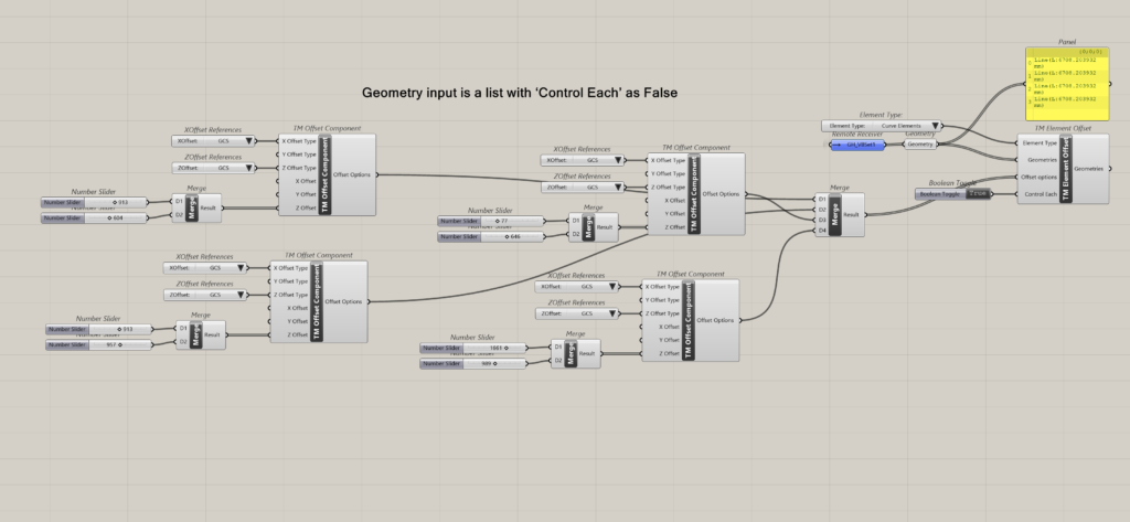
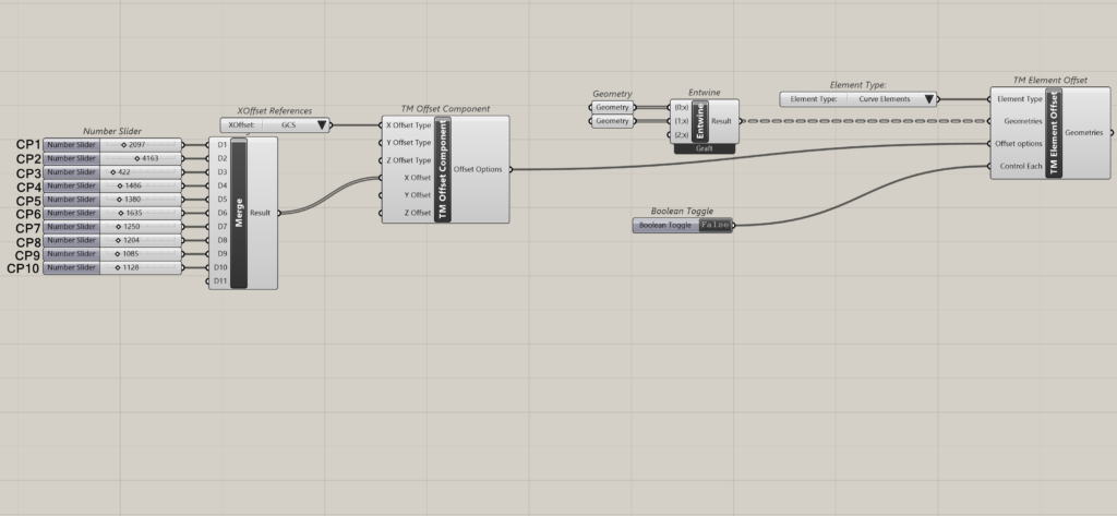
Geometry input is a list with ‘Control Each’ as False
Only one ‘TM offset’ component need be attached. It controls all the geometry inputs together. Ideal for situations where all the geometries in the list are subjected to offsets of same distances.
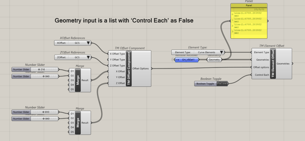
In the above example one ‘TM Offset’ component is used to control all four lines.
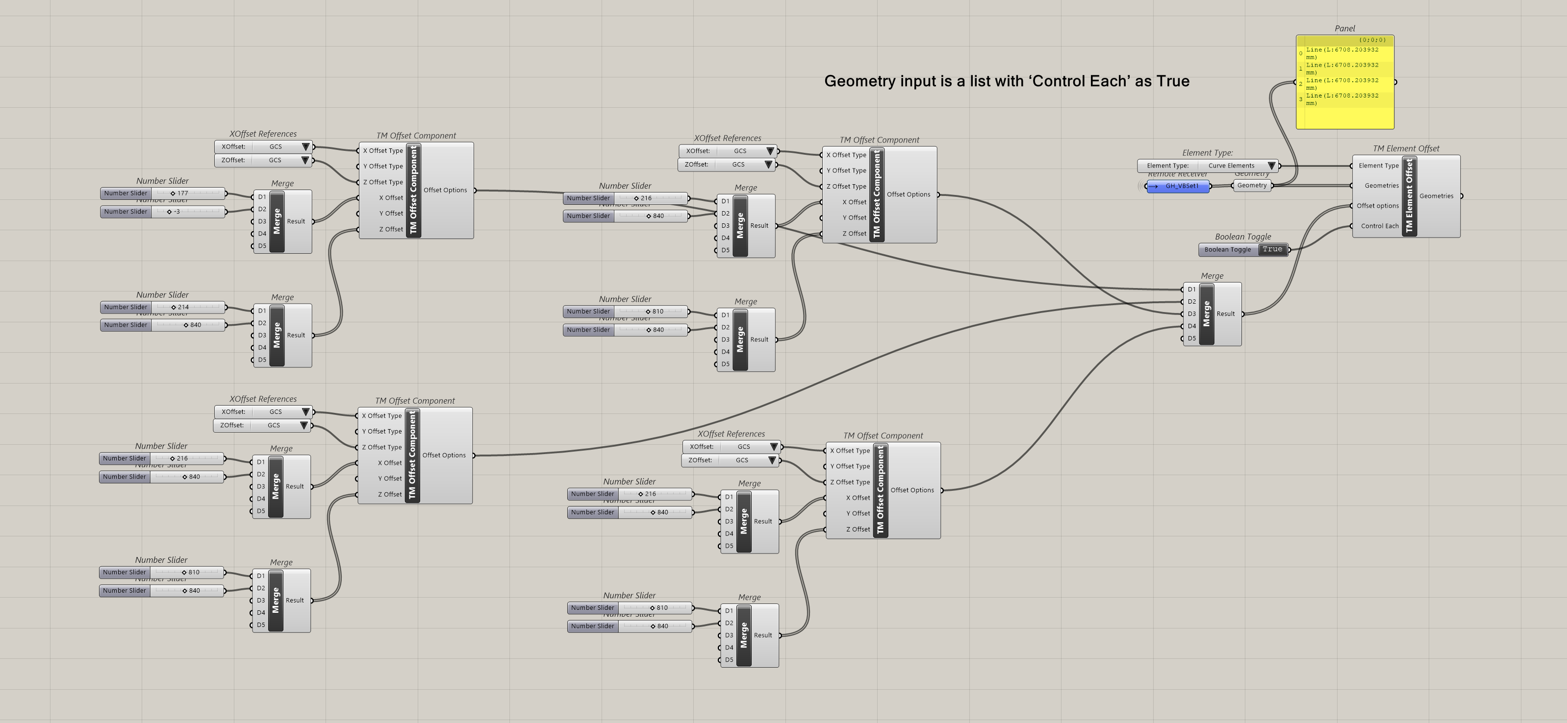
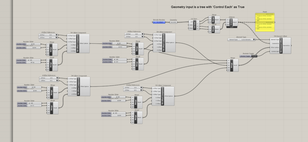
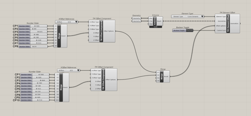
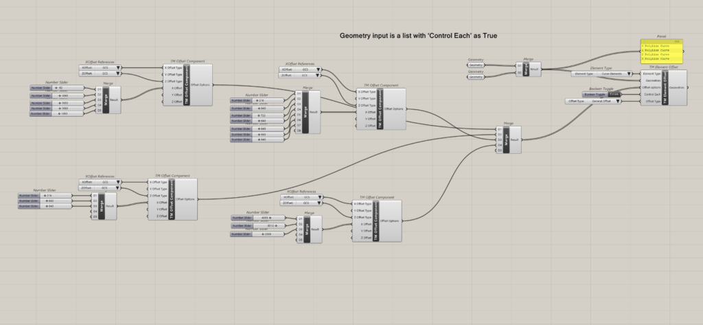
Geometry Input is a list with ‘Control Each’ as true
In this scenario, one can attach as many TM Offset’ Components as the no. of geometries that have been input and control the offsets of each geometry individually.
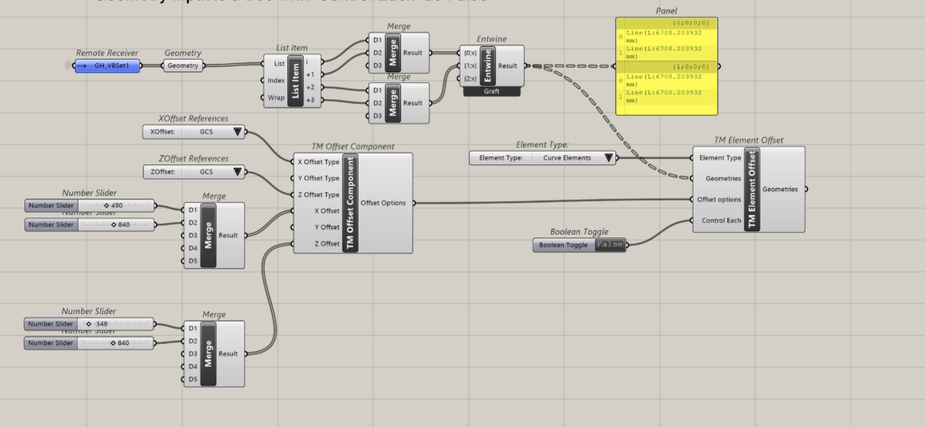
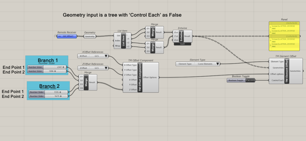
Geometry input is a tree with ‘Control Each’ as False
In this scenario, only one ‘TM Offset’ Component need be attached to control all the geometries together.
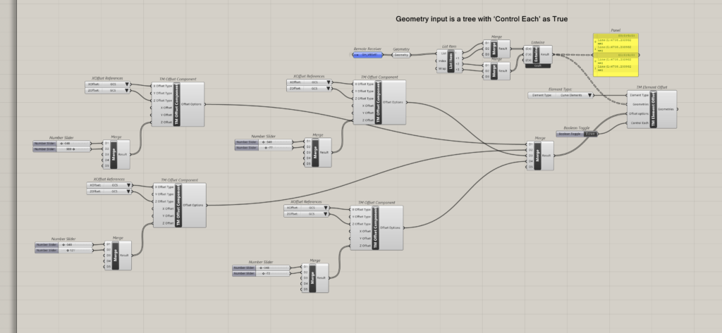
Geometry input is a tree with ‘Control Each’ as True
In this scenario, one can attach as many TM Offset’ Components as the no. of geometries that have been input, and control the offsets of each geometry individually. This is irrespective of the data structuring in the data tree format. Each item is considered a unique entity to be controlled.
Demo using ‘Branch Offset’ setting for lines with two control points i.e. only end points
Geometry input is a list with ‘Control Each’ as False
One offset component to control all geometries is enough; but the number of distance values to be fed is equal to end points corresponding to ‘n’ lines in the list i.e. ‘2n’. if there are four lines then one shall need to enter 8 distance offsets to the component.
Geometry input is a list with ‘Control Each’ as True
Attach as many TM offset components as the no. of geometries fed to the TM element offset components. Only Z offset is shown for clarity.
Geometry input is a tree with ‘Control Each’ as False
Takes only one TM Offset component for all the geometries. Feed as many offset distance values as the number of lines in each branch. In the current example there are two branches with two lines.
The first offset distance controls one set of end points of all the geometries in the first branch, the second offset distance controls the second set of end points of all the geometries in the same branch. The third offset distance controls the first set of end points of all the geometries in the second branch, the second offset distance controls the second set of end points of all the geometries in the second branch.
Geometry input is a tree with ‘Control Each’ as True
Attach as many TM offset components as the number of geometries across all the branches, to control each geometry individually.
Branch Offset- Lines with >2 Control Points
The following geometry is used to demonstrate the working of the component in case of geometries having multiple control points.
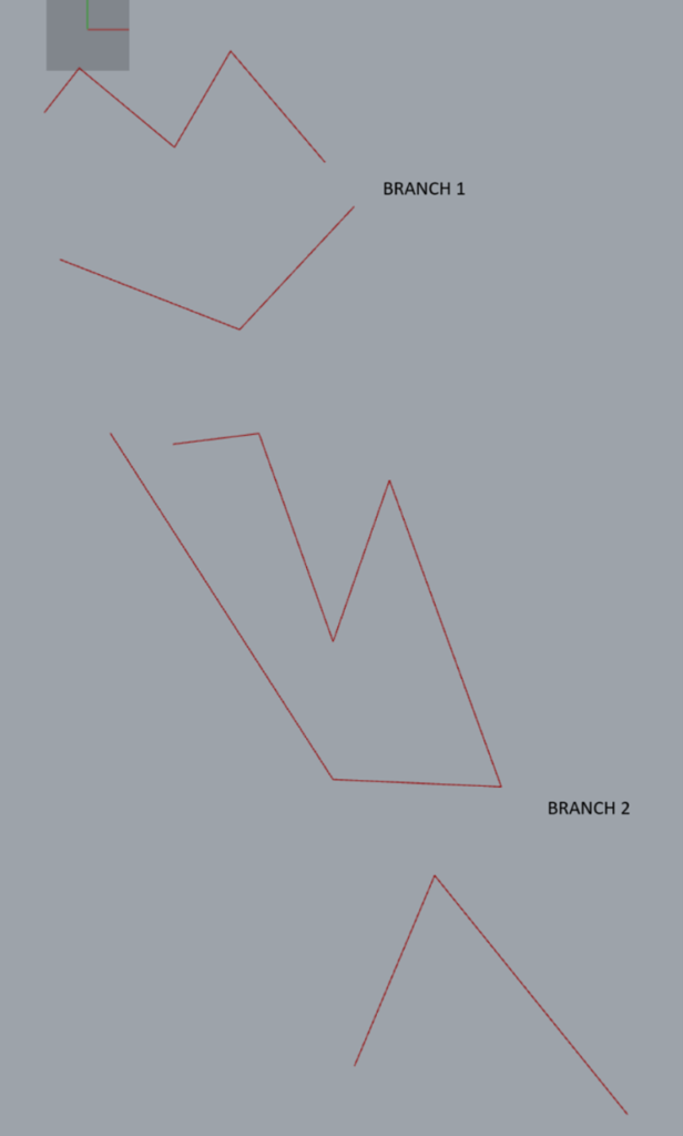
No. of control points
- Line 1: Branch 1: 5
- Line 2: Branch 1: 3
- Line 3: Branch 2: 7
- Line 4: Branch 2: 3
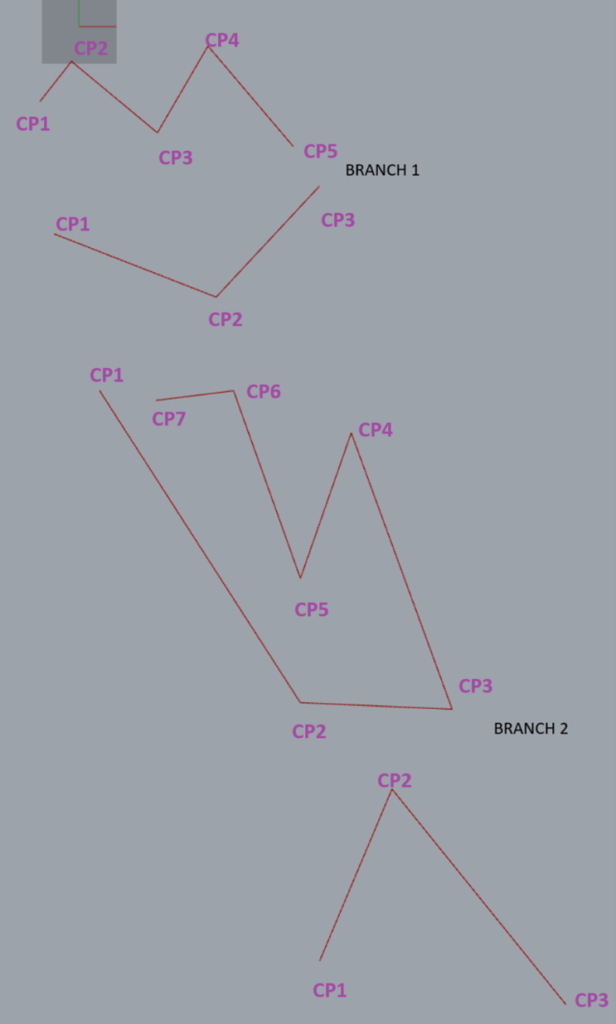
Geometry input is a tree with ‘Control Each’ as False-one TM Offset component
In this case only one ‘TM Offset’ component is required to control all the points. Notice which branch has maximum total number of control points (adding across all geometries in that branch). That shall be the number of offset distances to be fed to the TM offset component. In other words, No. of input distances should be equal to the branch containing the highest total no. of vertices.
In this case study the second branch has the highest number of control points i.e. 10.
Geometry input is a tree with ‘Control Each’ as False-Multiple TM Offset components
One can also control each branch individually, by attaching as many TM offset components as the number of branches of geometry fed.
In this case study as there are two branches, hence two TM Offset components have been attached.

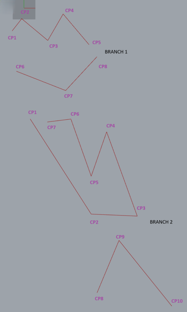
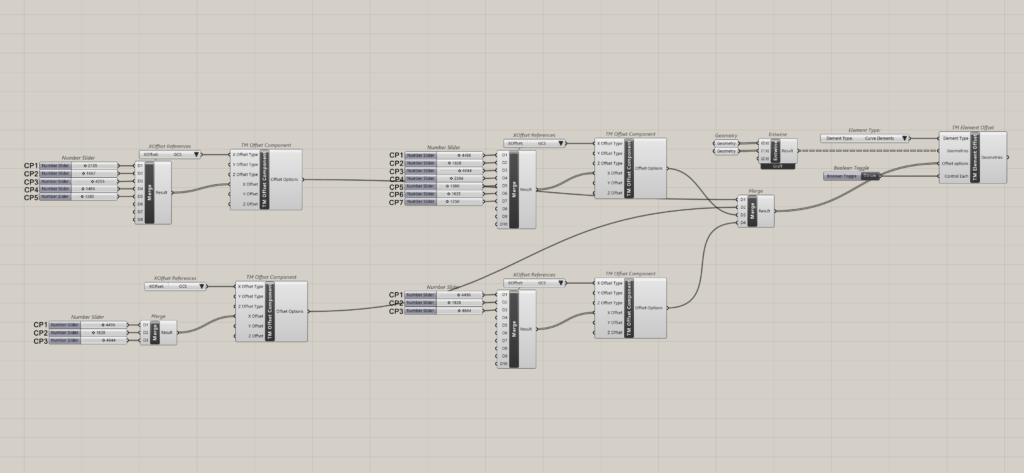
Geometry input is a tree with ‘Control Each’ as True
This arrangement imparts the ability to control each geometry individually. As there are four geometries in all the branches combined, four TM Offset components have been attached as shown below.

General Offset-Lines with >2 Control Points
The same lines as in branch offset have been used but converted into a single list.
Geometry input is a list with ‘Control Each’ as False
Takes a single ‘TM Offset’ component. Add as many offset distances as the line containing the highest number of control points.
In this case study one line has 7 control points which is the highest, and hence 7 offset distances have been fed.
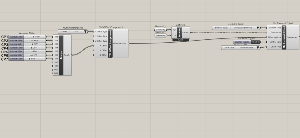
Geometry input is a list with ‘Control Each’ as True
Attach as many TM Offset components as the number of geometries, with corresponding control points. For e.g. the third line has 7 control points and hence 7 seven offset distances have been attached.
If the offset is zero, feed ‘0’ but make sure to feed the number.
Geometry inputs is a tree with ‘Control Each’ as False
Attach one ‘TM offset’ component to control all curves. Feed offset distances corresponding to the curve having the highest number of control points.
Geometry input is a tree with ‘Control Each’ as True
Attach as many TM offset components as the number of geometries, with offset distances corresponding to the control points on each curve.